Toyota Tacoma (2015-2018) Service Manual: On-vehicle Inspection
ON-VEHICLE INSPECTION
PROCEDURE
1. INSPECT ENGINE COOLANT
(See page .gif) )
)
2. INSPECT ENGINE OIL
(See page )
3. INSPECT BATTERY
(See page )
4. INSPECT SPARK PLUG
(See page )
5. INSPECT AIR CLEANER FILTER ELEMENT SUB-ASSEMBLY
(a) Remove the air cleaner filter element sub-assembly.
(b) Visually check that there is no dirt, blockage, and/or damage to the air cleaner filter element.
HINT:
- If there is any dirt or a blockage in the air cleaner filter element, clean it with compressed air.
- If any dirt or a blockage remains even after cleaning the air cleaner filter element with compressed air, replace it.
6. INSPECT V-RIBBED BELT TENSIONER ASSEMBLY
(a) Remove the fan and generator V belt (See page
).
(b) Check that nothing is caught in the tensioner by turning it clockwise and counterclockwise.
If a malfunction exists, replace the V-ribbed belt tensioner.
(c) Install the fan and generator V belt (See page
).
7. INSPECT VALVE LASH ADJUSTER NOISE
(a) Rev up the engine several times. Check that the engine does not emit unusual noises.
If unusual noises occur, warm up the engine and idle it for over 30 minutes. Then perform the inspection above again.
If any defects or problems are found during the inspection above, perform a lash adjuster inspection.
8. INSPECT IGNITION TIMING
(a) Warm up the engine and stop the engine.
NOTICE:
A warmed up engine should have an engine coolant temperature of over 85°C (185°F), and an engine oil temperature of 60°C (140°F), and the engine speed should be stabilized.
(b) When using the Techstream:
(1) Connect the Techstream to the DLC3.
(2) Start the engine and idle it.
(3) Turn the Techstream on.
(4) Enter the following menus: Powertrain / Engine / Data List / Ignition Timing Cylinder #1.
Standard Ignition Timing:
|
Transmission |
Ignition Timing |
|---|---|
|
Manual Transmission |
7 to 24° BTDC at idle |
|
Automatic Transmission |
7 to 24° BTDC at idle |
NOTICE:
When checking the ignition timing, the transmission should be in neutral or park.
HINT:
Refer to the Techstream operator's manual for further details.
(5) Check that the ignition timing advances immediately when the engine speed is increased.
(6) Enter the following menus: Powertrain / Engine / Active Test / Activate the TC Terminal.
(7) Monitor Ignition Timing Cylinder #1.
(8) Perform the Active Test.
Standard Ignition Timing:
|
Transmission |
Ignition Timing |
|---|---|
|
Manual Transmission |
8 to 12° BTDC at idle |
|
Automatic Transmission |
8 to 12° BTDC at idle |
NOTICE:
When checking the ignition timing, the transmission should be in neutral or park.
HINT:
Refer to the Techstream operator's manual for further details.
(c) When not using the Techstream:
(1) Remove the V-bank cover sub-assembly.
(2) Connect the tester probe of a timing light to the wire of the ignition connector for No. 1 cylinder.
NOTICE:
Use a timing light which can detect the primary signal.
|
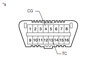
(3) Using SST, connect terminals 13 (TC) and 4 (CG) of the DLC3. Text in Illustration
SST: 09843-18040 NOTICE:
|
|
(4) Using a timing light, check the ignition timing.
Standard Ignition Timing:
|
Transmission |
Ignition Timing |
|---|---|
|
Manual Transmission |
8 to 12° BTDC at idle |
|
Automatic Transmission |
8 to 12° BTDC at idle |
(5) Remove SST from the DLC3.
(6) Check the ignition timing.
Standard Ignition Timing:
|
Transmission |
Ignition Timing |
|---|---|
|
Manual Transmission |
7 to 24° BTDC at idle |
|
Automatic Transmission |
7 to 24° BTDC at idle |
(7) Check that the ignition timing advances immediately when the engine speed is increased.
(8) Disconnect the timing light from the engine.
(9) Install the V-bank cover sub-assembly.
9. INSPECT ENGINE IDLE SPEED
(a) Warm up and stop the engine.
NOTICE:
A warmed up engine should have an engine coolant temperature of over 85°C (185°F) and an engine oil temperature of 60°C (140°F), and the engine speed should be stabilized.
(b) When using the Techstream:
(1) Connect the Techstream to the DLC3.
NOTICE:
Switch off all accessories and A/C before connecting the Techstream.
(2) Race the engine at 2500 rpm for approx. 90 seconds.
(3) Turn the Techstream on.
(4) Enter the following menus: powertrain / Engine / Data list / Engine Speed.
Standard Idle Speed:
|
Transmission |
Idling Speed |
|---|---|
|
Manual Transmission |
500 to 600 rpm |
|
Automatic Transmission |
550 to 650 rpm |
NOTICE:
When checking the idle speed, the transmission should be in neutral or park.
HINT:
Refer to the Techstream operator's manual for further details.
If the idle speed is not as specified, check the air intake system.
(5) Disconnect the Techstream from the DLC3.
(c) When not using the Techstream:
|
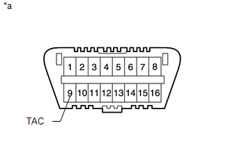
(1) Using SST, connect the tachometer probe to terminal 9 (TAC) of the DLC3. Text in Illustration
SST: 09843-18040 NOTICE: Confirm the terminal numbers before connecting them. Connecting the wrong terminals can damage the engine. |
|
(2) Race the engine at 2500 rpm for approx. 90 seconds.
(3) Check the idle speed.
Standard Idle Speed:
|
Transmission |
Idling Speed |
|---|---|
|
Manual Transmission |
500 to 600 rpm |
|
Automatic Transmission |
550 to 650 rpm |
NOTICE:
When checking the idle speed, the transmission should be in neutral or park.
If the speed is not as specified, check the air intake system.
(4) Disconnect the tachometer from the DLC3.
(d) Clear the DTCs (See page ).
NOTICE:
After the inspection, clear the DTCs, check for DTCs again and make sure the normal system code is output.
10. INSPECT COMPRESSION
(a) Warm up and stop the engine.
NOTICE:
A warmed up engine should have an engine coolant temperature of over 85°C (185°F) and an engine oil temperature of 60°C (140°F), and the engine speed should be stabilized.
(b) Remove the intake air surge tank (See page
).
(c) Remove the 6 spark plugs (See page ).
(d) Remove the engine room relay block cover.
(e) Remove the EFI-MAIN No. 2 relay from the engine room relay block.
(f) Insert a compression gauge into the spark plug hole.
(g) Fully open the throttle.
(h) While cranking the engine, measure the compression pressure.
Standard compression pressure:
1400 kPa (14.3 kgf/cm2, 199 psi) or higher
Minimum pressure:
980 kPa (10.0 kgf/cm2, 142 psi)
NOTICE:
The measurement must be done as quickly as possible.
HINT:
Always use a fully charged battery to obtain an engine speed of 250 rpm or more.
(i) Perform the inspection above for each cylinder.
Difference between each cylinder:
100 kPa (1.0 kgf/cm2, 15 psi) or less
(j) If the cylinder compression in one or more cylinders is low, pour a small amount of engine oil into the cylinder through the spark plug hole. Then perform the first 3 steps under "inspect the cylinder compression pressure" for the cylinders with low compression.
HINT:
- If adding oil helps boost the compression, it is likely that the piston rings and/or cylinder bore is worn or damaged.
- If pressure stays low, a valve may be stuck or seated improperly, or there may be leakage in the gasket.
(k) Install the EFI-MAIN No. 2 relay to the engine room relay block.
(l) Install the engine room relay block cover.
(m) Install the 6 spark plugs (See page ).
(n) Install the intake air surge tank (See page
).
11. INSPECT CO/HC
HINT:
This is a check for determining whether or not the idle CO / HC complies with regulations.
(a) Start the engine.
(b) Keep the engine speed at 2500 rpm for approx. 180 seconds.
(c) Insert the CO / HC meter testing probe at least 40 cm (1.31 ft.) into the tailpipe during idling.
(d) Immediately check the CO / HC concentration at idle and/or 2500 rpm.
HINT:
- When performing the 2 mode (2500 rpm and idle) test, follow the measurement order prescribed by the applicable local regulations.
- If the CO / HC concentration does not comply with regulations, troubleshoot in the order given below.
(1) Check the DTCs (See page ).
(2) See the table below for possible causes, then inspect and correct the applicable causes if necessary.
|
CO |
HC |
Symptom |
Causes |
|---|---|---|---|
|
Normal |
High |
Rough idle |
|
|
Low |
High |
Rough idle (Fluctuating HC reading) |
|
|
High |
High |
Rough idle (Black smoke from exhaust) |
|
 Engine
...
 Engine Unit
...
Other materials:
Precaution
PRECAUTION
1. DOOR CONTROL RECEIVER EXPRESSIONS
(a) The type of door control receiver used on this model differs according to
the specifications of the vehicle. The expressions listed in the table below are
used in this section.
Vehicle Specification
Part Name in Manual
...
IG Signal Circuit
DESCRIPTION
This circuit detects whether the ignition switch is ON or off, and sends this
information to the main body ECU (multiplex network body ECU).
WIRING DIAGRAM
CAUTION / NOTICE / HINT
NOTICE:
Inspect the fuses for circuits related to this system before performing
the fol ...
Center Differential Lock Position Switch (C1282)
DESCRIPTION
DTC C1282 is stored only in test mode.
DTC Code
DTC Detection Condition
Trouble Area
C1282
Stored during test mode.
Harness or connector
Transfer system
Skid control ECU (master cylinder sole ...
