Toyota Tacoma (2015-2018) Service Manual: Combination Meter
Components
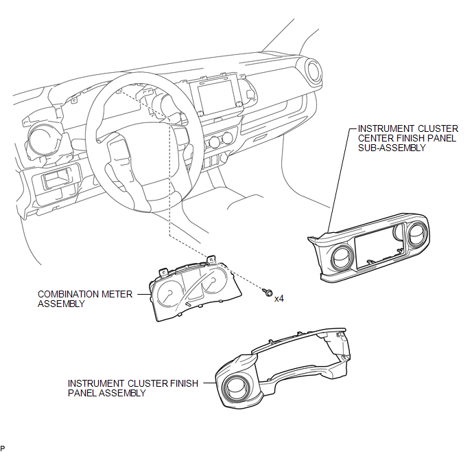
COMPONENTS
ILLUSTRATION
Removal
REMOVAL
PROCEDURE
1. PRECAUTION
NOTICE:
After turning the ignition switch off, waiting time may be required before disconnecting the cable from the negative (-) battery terminal. Therefore, make sure to read the disconnecting the cable from the negative (-) battery terminal notices before proceeding with work.
Click here .gif)
2. DISCONNECT CABLE FROM NEGATIVE BATTERY TERMINAL
NOTICE:
When disconnecting the cable, some systems need to be initialized after the cable is reconnected.
Click here
3. REMOVE INSTRUMENT CLUSTER CENTER FINISH PANEL SUB-ASSEMBLY
Click here
4. REMOVE INSTRUMENT CLUSTER FINISH PANEL ASSEMBLY
Click here
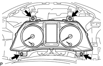
5. REMOVE COMBINATION METER ASSEMBLY
|
(a) Remove the 4 screws. |
|
|
(b) Disengage the clamp. |
|
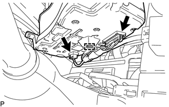
(c) Disconnect the 2 connectors to remove the combination meter assembly.
Installation
INSTALLATION
PROCEDURE
1. INSTALL COMBINATION METER ASSEMBLY
(a) Connect the 2 connectors.
(b) Engage the clamp.
(c) Install the combination meter assembly with the 4 screws.
2. INSTALL INSTRUMENT CLUSTER FINISH PANEL ASSEMBLY
Click here .gif)
3. INSTALL INSTRUMENT CLUSTER CENTER FINISH PANEL SUB-ASSEMBLY
Click here
4. CONNECT CABLE TO NEGATIVE BATTERY TERMINAL
Torque:
5.4 N·m {55 kgf·cm, 48 in·lbf}
NOTICE:
When disconnecting the cable, some systems need to be initialized after the cable is reconnected.
Click here


Other materials:
Data List / Active Test
DATA LIST / ACTIVE TEST
DATA LIST
HINT:
Using the Techstream to read the Data List allows the values or states of switches,
sensors, actuators and other items to be read without removing any parts. This non-intrusive
inspection can be very useful because intermittent conditions or signals may ...
Diagnostic Trouble Code Chart
DIAGNOSTIC TROUBLE CODE CHART
Steering Lock System
DTC Code
Detection Item
See page
B2781
Open / Short in Steering Lock ECU
B2782
Power Source Control ECU Malfunction
...
Open in Bus 3 Main Bus Line
DESCRIPTION
There may be an open circuit in one of the CAN main bus lines when the resistance
between terminals 6 (CA3H) and 21 (CA3L) of the central gateway ECU (network gateway
ECU) is 70 Ω or higher.
Detection Item
Trouble Area
Resistance between term ...
