Toyota Tacoma (2015-2018) Service Manual: Removal
REMOVAL
PROCEDURE
1. PRECAUTION
NOTICE:
After turning the ignition switch off, waiting time may be required before disconnecting the cable from the negative (-) battery terminal. Therefore, make sure to read the disconnecting the cable from the negative (-) battery terminal notices before proceeding with work.
Click here .gif)
2. DISCONNECT CABLE FROM NEGATIVE BATTERY TERMINAL
NOTICE:
When disconnecting the cable, some systems need to be initialized after the cable is reconnected.
Click here
3. DISCONNECT CABLE FROM POSITIVE BATTERY TERMINAL
4. REMOVE BATTERY CLAMP SUB-ASSEMBLY
(a) Loosen the nut and remove the battery clamp sub-assembly.
5. REMOVE BATTERY
6. REMOVE BATTERY TRAY
7. REMOVE V-BANK COVER
Click here
8. REMOVE FAN AND GENERATOR V BELT
Click here
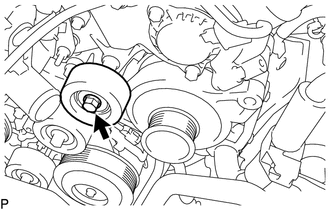
9. REMOVE NO. 2 IDLER PULLEY SUB-ASSEMBLY
|
(a) Remove the bolt and No. 2 idler pulley sub-assembly. |
|
10. REMOVE NO. 1 SURGE TANK STAY
Click here
11. REMOVE GENERATOR ASSEMBLY
|
(a) Disengage the clamp and disconnect the engine wire from the wire harness clamp bracket. |
|
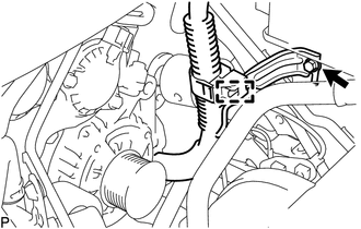
(b) Remove the bolt and wire harness clamp bracket.
|
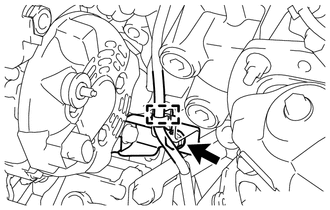
(c) Disconnect the connector from the generator assembly. |
|
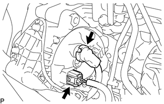
(d) Remove the terminal cap.
(e) Remove the nut and disconnect the engine wire from the terminal B.
|
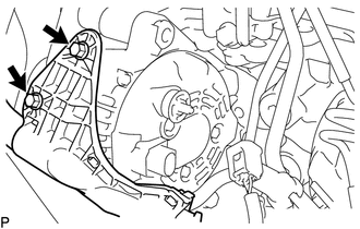
(f) Remove the 2 bolts and disconnect the engine wire from the generator assembly. |
|
|
(g) Disengage the clamp and disconnect the engine wire from the wire harness clamp bracket |
|
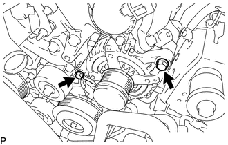
(h) Remove the bolt and disconnect the generator bracket from the cylinder block sub-assembly.
|
(i) Remove the 2 bolts and generator assembly. |
|
|
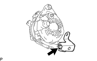
(j) Remove the bolt and generator bracket from the generator assembly. |
|
 Components
COMPONENTS
ILLUSTRATION
ILLUSTRATION
...
 Disassembly
DISASSEMBLY
PROCEDURE
1. REMOVE GENERATOR PULLEY
(a) Mount the generator assembly in the vise between aluminum plates.
NOTICE:
Do not overtighten the vise.
(b) Install SST 1-A to the generator p ...
Other materials:
Diagnosis System
DIAGNOSIS SYSTEM
1. DESCRIPTION
(a) The steering lock ECU (steering lock actuator or UPR bracket assembly) stores
DTCs when a malfunction occurs in the system. These DTCs can be confirmed by using
the Techstream.
NOTICE:
When using the Techstream with the engine switch off to confirm ...
Accelerator Pedal
Components
COMPONENTS
ILLUSTRATION
On-vehicle Inspection
ON-VEHICLE INSPECTION
PROCEDURE
1. INSPECT ACCELERATOR PEDAL SENSOR ASSEMBLY
(a) Connect the Techstream to the DLC3.
(b) Turn the ignition switch to ON.
(c) Turn the Techstream on.
(d) Enter the following menus: Powertrain / En ...
System Description
SYSTEM DESCRIPTION
1. TOUCH SWITCH OUTLINE
Touch switches are touch-sensitive (interactive) switches operated by touching
the screen. When a switch is pressed, the outer film bends in to contact the inner
glass at the pressed position. By doing this, the voltage ratio is measured and
the pre ...
