Toyota Tacoma (2015-2018) Service Manual: Low Power Supply Voltage Malfunction (C1241)
DESCRIPTION
If there is a problem with the skid control ECU (master cylinder solenoid) power supply circuit, the skid control ECU outputs the DTC and prohibits operation under the fail-safe function.
If the voltage supplied to terminal IG1 is not within the DTC detection threshold due to malfunctions in parts such as the battery and generator circuit, this DTC is stored.
|
DTC Code |
DTC Detection Condition |
Trouble Area |
|---|---|---|
|
C1241 |
When either of following conditions detected: 1. Both of following conditions continue for at least 10 seconds.
2. All of following conditions continue for at least 0.2 seconds.
|
|
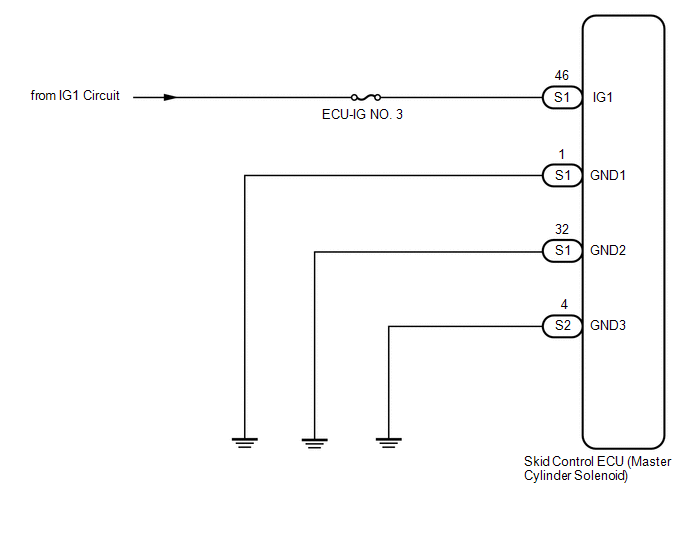
WIRING DIAGRAM
CAUTION / NOTICE / HINT
NOTICE:
- When replacing the skid control ECU (master cylinder solenoid), perform
zero point calibration (See page
.gif) ).
). - Inspect the fuses for circuits related to this system before performing the following inspection procedure.
PROCEDURE
|
1. |
READ VALUE USING TECHSTREAM (IG VOLTAGE) |
(a) Turn the ignition switch off.
(b) Connect the Techstream to the DLC3.
(c) Turn the ignition switch to ON.
(d) Turn the Techstream on.
(e) Start the engine.
(f) Enter the following menus: Chassis / ABS/VSC/TRAC / Data List.
ABS/VSC/TRAC|
Tester Display |
Measurement Item : Range |
Normal Condition |
Diagnostic Note |
|---|---|---|---|
|
IG1 Voltage Value |
IG1 voltage value/ Min.: 0.00 V, Max.: 20.00 V |
11 to 14 V |
Changes in proportion to battery voltage |
(g) Measure the voltage output from the ECU displayed on the Techstream.
Result|
Result |
Proceed |
|---|---|
|
Data display is within Normal Condition |
A |
|
Data display is not within Normal Condition |
B |
| B | .gif) |
GO TO STEP 3 |
|
.gif)
|
2. |
RECONFIRM DTC |
(a) Clear the DTCs (See page
).
(b) Turn the ignition switch off.
(c) Check if the same DTCs are output (See page
).
HINT:
Reinstall the sensors, connectors, etc. and restore the previous vehicle conditions before rechecking for DTCs.
Result|
Result |
Proceed to |
|---|---|
|
DTC is output |
A |
|
DTC is not output (When troubleshooting in accordance with Diagnostic Trouble Code Chart) |
B |
|
DTC is not output (When troubleshooting in accordance with Problem Symptoms Table) |
C |
| A | |
REPLACE MASTER CYLINDER SOLENOID |
| B | |
USE SIMULATION METHOD TO CHECK |
| C | |
PROCEED TO NEXT SUSPECTED AREA SHOWN IN PROBLEM SYMPTOMS TABLE |
|
3. |
CHECK HARNESS AND CONNECTOR (IG1 TERMINAL) |
|
(a) Disconnect the skid control ECU (master cylinder solenoid) connector. |
|
(b) Measure the voltage according to the value(s) in the table below.
Standard Voltage:
|
Tester Connection |
Switch Condition |
Specified Condition |
|---|---|---|
|
S1-46 (IG1) - Body ground |
Ignition switch ON |
11 to 14 V |
|
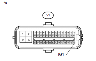
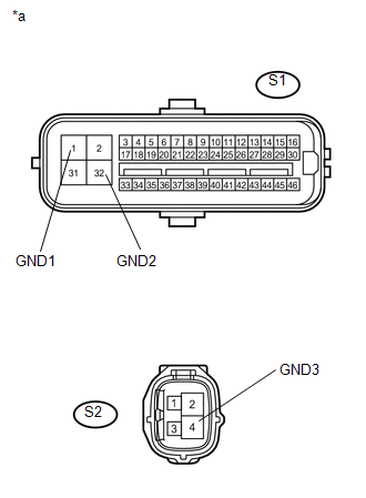
*a |
Front view of wire harness connector (to Skid Control ECU (Master Cylinder Solenoid)) |
| NG | |
REPAIR OR REPLACE HARNESS OR CONNECTOR |
|
|
4. |
CHECK HARNESS AND CONNECTOR (GND TERMINAL) |
|
(a) Measure the resistance according to the value(s) in the table below. Standard Resistance:
|
|
| NG | |
REPAIR OR REPLACE HARNESS OR CONNECTOR |
|
|
5. |
RECONFIRM DTC |
(a) Clear the DTCs (See page
).
(b) Turn the ignition switch off.
(c) Check if the same DTCs are output (See page
).
HINT:
Reinstall the sensors, connectors, etc. and restore the previous vehicle conditions before rechecking for DTCs.
Result|
Result |
Proceed to |
|---|---|
|
DTC is output |
A |
|
DTC is not output (When troubleshooting in accordance with Diagnostic Trouble Code Chart) |
B |
|
DTC is not output (When troubleshooting in accordance with Problem Symptoms Table) |
C |
| A | |
REPLACE MASTER CYLINDER SOLENOID |
| B | |
USE SIMULATION METHOD TO CHECK |
| C | |
PROCEED TO NEXT SUSPECTED AREA SHOWN IN PROBLEM SYMPTOMS TABLE |
 Acceleration Sensor Stuck Malfunction (C1232,C1243,C1245,C1279)
DESCRIPTION
The skid control ECU (master cylinder solenoid) receives signals from the yaw
rate and acceleration (airbag sensor assembly) via the CAN communication system.
The airbag sensor assembl ...
 Open Circuit in IG1/IG2 Power Source Circuit (C1242)
DESCRIPTION
If there is a problem with the skid control ECU (master cylinder solenoid) power
supply circuit, the skid control ECU outputs the DTC and prohibits operation under
the fail safe funct ...
Other materials:
If your vehicle has to be stopped in an emergency
Only in an emergency, such as if it becomes impossible to stop the vehicle
in the normal way, stop the vehicle using the following procedure:
Steadily step on the brake pedal
with both feet and firmly depress it.
Do not pump the brake pedal repeatedly as this will increase the effort required ...
Problem Symptoms Table
PROBLEM SYMPTOMS TABLE
HINT:
Use the table below to help determine the cause of problem symptoms.
If multiple suspected areas are listed, the potential causes of the symptoms
are listed in order of probability in the "Suspected Area" column of the
table. Check each sy ...
Open in ABS Solenoid Relay Circuit (C146E,C146F)
DESCRIPTION
The ABS solenoid relay supplies power to the ABS solenoid and TRAC solenoid.
The solenoid relay is turned on 1.5 seconds after the ignition switch is turned
ON, and is turned off if an open or short in the solenoid is detected by the self
diagnosis performed when the engine starts ...
