Toyota Tacoma (2015-2018) Service Manual: On-vehicle Inspection
ON-VEHICLE INSPECTION
PROCEDURE
1. INSPECT LOWER NO. 2 INSTRUMENT PANEL AIRBAG ASSEMBLY (for Vehicle not Involved in Collision)
|
(a) Perform a diagnostic system check (See page
|
|
.gif) ).
).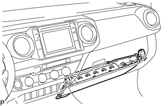
(b) With the lower No. 2 instrument panel airbag assembly installed on the vehicle, perform a visual check. If there are any defects as mentioned below, replace the lower No. 2 instrument panel airbag assembly with a new one:
Cuts, minute cracks or marked discoloration on the lower No. 2 instrument panel airbag assembly.
2. INSPECT LOWER NO. 2 INSTRUMENT PANEL AIRBAG ASSEMBLY (for Vehicle Involved in Collision and Airbag has not Deployed)
|
(a) Perform a diagnostic system check (See page
|
|
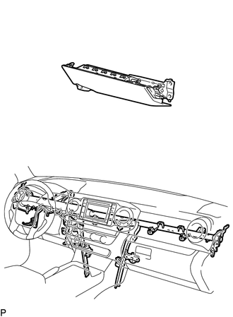
(b) With the lower No. 2 instrument panel airbag assembly removed from the vehicle, perform a visual check. If there are any defects as mentioned below, replace the lower No. 2 instrument panel airbag assembly with a new one:
- Cuts, minute cracks or marked discoloration on the lower No. 2 instrument panel airbag assembly.
- Cracks or other damage to the connector.
- Deformation or cracks on the instrument panel reinforcement.
CAUTION:
For removal and installation procedures of the lower No. 2 instrument panel airbag assembly, be sure to follow the correct procedure.
 Installation
INSTALLATION
PROCEDURE
1. INSTALL LOWER NO. 2 INSTRUMENT PANEL AIRBAG ASSEMBLY
(a) Connect the airbag connector.
NOTICE:
When handling the airbag connector, take care not to damage ...
 Removal
REMOVAL
PROCEDURE
1. PRECAUTION
CAUTION:
Be sure to read Precaution thoroughly before servicing (See page
).
NOTICE:
After turning the ignition switch off, waiting time may be required before ...
Other materials:
Slip Indicator Light Remains ON
DESCRIPTION
The slip indicator light blinks during VSC or TRAC and AUTO LSD operation. When
the system fails, the slip indicator light comes on to warn the driver.
WIRING DIAGRAM
CAUTION / NOTICE / HINT
NOTICE:
When replacing the skid control ECU (master cylinder solenoid), perform ...
4wd Control Ecu
Components
COMPONENTS
ILLUSTRATION
Installation
INSTALLATION
PROCEDURE
1. INSTALL 4 WHEEL DRIVE CONTROL ECU
(a) Engage the 2 guides to install the 4 wheel drive control ECU.
(b) Install the 2 bolts.
Torque:
5.0 N·m {51 kgf·cm, 44 in·lbf}
(c) Connect the 2 connectors.
2. INSTALL ...
Certification ECU Vehicle Information Reading/Writing Process Malfunction (B15F7)
DESCRIPTION
This DTC is stored when items controlled by the certification ECU (smart key
ECU assembly) cannot be customized via the navigation system vehicle customization
screen.
HINT:
The certification ECU (smart key ECU assembly) controls the smart key system
related items that are custo ...
