Toyota Tacoma (2015-2018) Service Manual: Removal
REMOVAL
PROCEDURE
1. PRECAUTION
CAUTION:
Be sure to read Precaution thoroughly before servicing (See page
.gif) ).
).
NOTICE:
After turning the ignition switch off, waiting time may be required before disconnecting the cable from the negative (-) battery terminal. Therefore, make sure to read the disconnecting the cable from the negative (-) battery terminal notices before proceeding with work.
Click here
2. DISCONNECT CABLE FROM NEGATIVE BATTERY TERMINAL
CAUTION:
Wait at least 90 seconds after disconnecting the cable from the negative (-) battery terminal to prevent airbag and seat belt pretensioner activation.
NOTICE:
When disconnecting the cable, some systems need to be initialized after the cable is reconnected.
Click here
3. REMOVE INSTRUMENT SIDE PANEL RH
4. REMOVE GLOVE COMPARTMENT PLATE
5. REMOVE LOWER NO. 2 INSTRUMENT PANEL AIRBAG ASSEMBLY
|
(a) Remove the 3 bolts. Text in Illustration
|
|
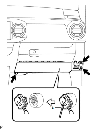
(b) Using a screwdriver with its tip wrapped in protective tape, release the airbag connector lock.
(c) Disconnect the airbag connector to remove the lower No. 2 instrument panel airbag assembly.
NOTICE:
When handling the airbag connector, take care not to damage the airbag wire harness.
 On-vehicle Inspection
ON-VEHICLE INSPECTION
PROCEDURE
1. INSPECT LOWER NO. 2 INSTRUMENT PANEL AIRBAG ASSEMBLY (for Vehicle not Involved
in Collision)
(a) Perform a diagnostic system check (See page
).
...
 Disposal
DISPOSAL
CAUTION / NOTICE / HINT
CAUTION:
Before performing pre-disposal deployment of any SRS part, review and closely
follow all applicable environmental and hazardous material regulations. Pre ...
Other materials:
Transfer Shift Motor Limit Switch Circuit (P17AC)
DESCRIPTION
When the transfer switches modes, the TL1, TL2 and TL3 terminals of the limit
switch are in one of the ON/OFF combinations listed in the table below.
Terminal
When 2WD
Switching between 2WD and H4
When H4
Switching between H4 and ...
Propeller Shaft System
Problem Symptoms Table
PROBLEM SYMPTOMS TABLE
HINT:
Use the table below to help determine the cause of problem symptoms. If multiple
suspected areas are listed, the potential causes of the symptoms are listed in order
of probability in the "Suspected Area" column of the table. Che ...
Open in Bus 3 Main Bus Line
DESCRIPTION
There may be an open circuit in one of the CAN main bus lines when the resistance
between terminals 6 (CA3H) and 21 (CA3L) of the central gateway ECU (network gateway
ECU) is 70 Ω or higher.
Detection Item
Trouble Area
Resistance between term ...
