Toyota Tacoma (2015-2018) Service Manual: Installation
INSTALLATION
PROCEDURE
1. INSTALL LOWER NO. 2 INSTRUMENT PANEL AIRBAG ASSEMBLY
|
(a) Connect the airbag connector. NOTICE: When handling the airbag connector, take care not to damage the airbag wire harness. |
|
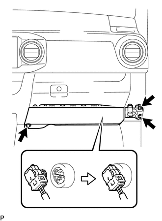
(b) Push in the airbag connector lock to install the airbag connector.
(c) Install the lower No. 2 instrument panel airbag assembly with the 3 bolts.
Torque:
10 N·m {102 kgf·cm, 7 ft·lbf}
2. INSTALL GLOVE COMPARTMENT PLATE
.gif)
3. INSTALL INSTRUMENT SIDE PANEL RH
4. CONNECT CABLE TO NEGATIVE BATTERY TERMINAL
Torque:
5.4 N·m {55 kgf·cm, 48 in·lbf}
NOTICE:
When disconnecting the cable, some systems need to be initialized after the cable is reconnected.
Click here
5. INSPECT SRS WARNING LIGHT
Click here
 Components
COMPONENTS
ILLUSTRATION
...
 On-vehicle Inspection
ON-VEHICLE INSPECTION
PROCEDURE
1. INSPECT LOWER NO. 2 INSTRUMENT PANEL AIRBAG ASSEMBLY (for Vehicle not Involved
in Collision)
(a) Perform a diagnostic system check (See page
).
...
Other materials:
Reassembly
REASSEMBLY
CAUTION / NOTICE / HINT
HINT:
The procedure described below is for the LH side. Use the same procedure for
both the LH and RH sides, unless otherwise specified.
PROCEDURE
1. INSTALL REAR SEAT CUSHION FRAME SUB-ASSEMBLY
(a) Install the rear seat cushion frame sub-assembl ...
Data List / Active Test
DATA LIST / ACTIVE TEST
1. DATA LIST
NOTICE:
In the table below, the values listed under "Normal Condition" are reference
values. Do not depend solely on these reference values when deciding whether a part
is faulty or not.
HINT:
Using the Techstream to read the Data List allows t ...
ECU Malfunction (B1003)
DESCRIPTION
DTC No.
DTC Detection Condition
Trouble Area
B1003
A malfunction in the non-volatile storage of the central gateway ECU
(network gateway ECU) is detected.
Central gateway ECU (network gateway ECU)
PROC ...
