Toyota Tacoma (2015-2018) Service Manual: Open in ABS Solenoid Relay Circuit (C146E,C146F)
DESCRIPTION
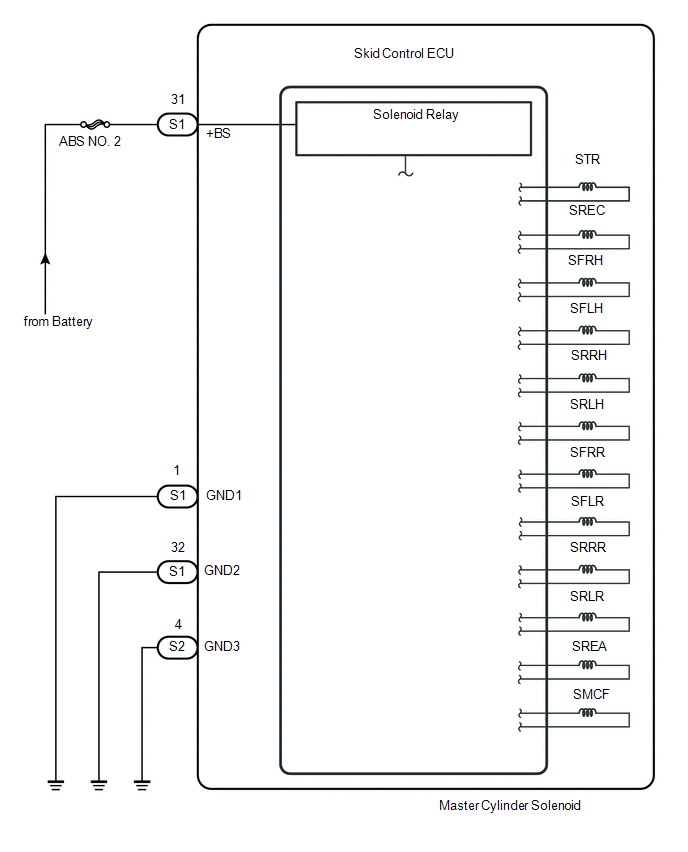
The ABS solenoid relay is built into the master cylinder solenoid.
This relay supplies power to each ABS solenoid. After the ignition switch is turned ON, if the initial check is OK, the relay turns on.
|
DTC No. |
DTC Detecting Conditions |
Trouble Areas |
|---|---|---|
|
C146E |
When either of following condition detected:
|
|
|
C146F |
The following condition continues for at least 0.2 seconds.
|
|
WIRING DIAGRAM
CAUTION / NOTICE / HINT
NOTICE:
- When replacing the skid control ECU (master cylinder solenoid), perform
zero point calibration (See page
.gif) ).
). - Inspect the fuses for circuits related to this system before performing the following inspection procedure.
PROCEDURE
|
1. |
INSPECT SKID CONTROL ECU CONNECTOR (+BS TERMINAL VOLTAGE) |
|
(a) Disconnect the skid control ECU connector. |
|
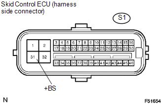
(b) Measure the voltage.
Standard Voltage:
|
Tester Connection |
Specified Condition |
|---|---|
|
S1-31 (+BS) - Body ground |
10 to 14 V |
(c) Reconnect the skid control ECU connector.
| NG | .gif) |
REPAIR OR REPLACE HARNESS OR CONNECTOR |
|
.gif)
|
2. |
CHECK HARNESS OR CONNECTOR (GND - BODY GROUND) |
|
(a) Disconnect the skid control ECU connectors. |
|
.png)
(b) Measure the resistance.
Standard Resistance:
|
Tester Connection |
Specified Condition |
|---|---|
|
S1-1, 32 (GND1, GND2) - Body ground |
Below 1 Ω |
|
S2-4 (GND3) - Body ground |
Below 1 Ω |
(c) Reconnect the skid control ECU connectors.
| NG | |
REPAIR OR REPLACE HARNESS OR CONNECTOR (GND CIRCUIT) |
|
|
3. |
RECONFIRM DTC |
(a) Clear the DTCs (See page
).
(b) Check if the same DTCs are recorded.
|
Result |
Proceed to |
|---|---|
|
DTC output |
A |
|
DTC not output |
B |
| A | |
REPLACE MASTER CYLINDER SOLENOID |
| B | |
END |
 Abnormal Change in Output Signal of Rear Speed Sensor RH (Test Mode DTC) (C1277,...,C1416)
DESCRIPTION
Refer to DTCs C1401 and C1402 (See page ).
DTC Code
DTC Detection Condition
Trouble Area
C1277
C1278
Stored only during t ...
 ECM Communication Circuit Malfunction (C1203)
DESCRIPTION
The circuit sends TRAC, A-TRAC and VSC control information from the skid control
ECU (master cylinder solenoid) to the ECM, and engine control information from the
ECM to the skid con ...
Other materials:
Reassembly
REASSEMBLY
PROCEDURE
1. INSPECT CENTER NO. 2 SUPPORT BEARING ASSEMBLY
(a) Turn the center bearing by hand, check that it turns smoothly without catching
and that there are no cracks or damage.
If there are any defects, replace it.
2. INSTALL CENTER NO. 2 SUPPORT BEARING ASSEMBLY
(a) Instal ...
Inspection
INSPECTION
PROCEDURE
1. INSPECT TIRES
(a) Check the tires for wear and proper inflation pressure.
Standard Cold Tire Inflation Pressure:
Tire Size
Front Wheel
kPa (kgf/cm2, psi)
Rear Wheel
kPa (kgf/cm2, psi)
Spare Wheel
kPa (kgf/cm2, psi)
...
Installation
INSTALLATION
PROCEDURE
1. REMOVE MONOLITHIC CONVERTER PROTECTOR
(a) Install the upper monolithic converter protector and lower monolithic converter
protector with the 2 bolts and 2 nuts.
Torque:
11 N·m {107 kgf·cm, 8 ft·lbf}
(b) Install the clamp with the bolt as shown in the ...
