
Toyota Tacoma (2015-2018) Service Manual: On-vehicle Inspection
ON-VEHICLE INSPECTION
PROCEDURE
1. INSPECT REFRIGERANT PRESSURE
(a) This method uses a refrigerant recovery unit set to locate problem areas. Read the refrigerant pressure when the test conditions are established.
Test conditions:
- Temperature at the air inlet with the air recirculation switch set at RECIRC is 30 to 35°C (86 to 95°F).
- Engine is running at 1500 rpm.
- All doors are fully open.
- Blower speed control switch is set to HI.
- A/C switch is on.
Gauge readings (Reference):
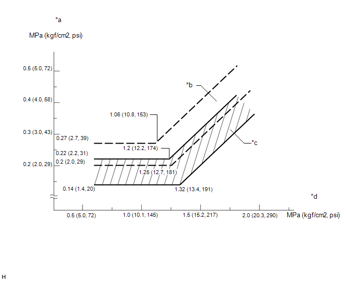 Text in Illustration
|
*a |
Pressure on low-pressure side |
*b |
Blower HI Zone |
|
*c |
Blower LO Zone |
*d |
Pressure on high-pressure side |
|
(1) Normally functioning refrigeration system. Gauge Reading:
|
|
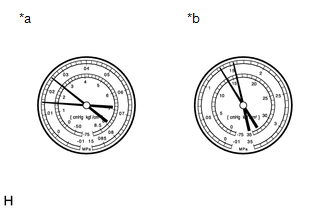
(2) The A/C system periodically changes between normal and improper function due to moisture in the refrigerant system.
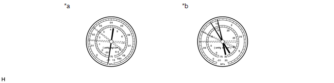 Text in Illustration
|
*a |
Low Pressure Side |
*b |
High Pressure Side |
|
Symptom |
Probable Cause |
Diagnosis |
Corrective Action |
|---|---|---|---|
|
During operation, pressure on low pressure side cycles between normal and vacuum |
Moisture in refrigeration system freezes at expansion valve orifice, causing temporary stop of cycle. However, when melted, normal state is restored. |
|
|
(3) The A/C system does not function effectively due to insufficient refrigerant.
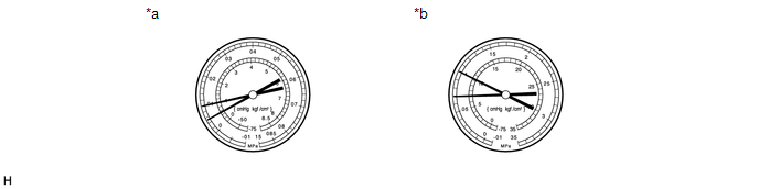 Text in Illustration
|
*a |
Low Pressure Side |
*b |
High Pressure Side |
|
Symptom |
Probable Cause |
Diagnosis |
Corrective Action |
|---|---|---|---|
|
Gas leakage from refrigeration system |
|
|
(4) The A/C system does not function effectively due to poor circulation of the refrigerant.
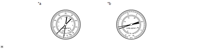 Text in Illustration
|
*a |
Low Pressure Side |
*b |
High Pressure Side |
|
Symptom |
Probable Cause |
Diagnosis |
Corrective Action |
|---|---|---|---|
|
Refrigerant flow obstructed by dirt in condenser |
Condenser clogged |
Replace condenser |
(5) The A/C system does not function or functions intermittently because the refrigerant does not circulate.
Text in Illustration
|
*a |
Low Pressure Side |
*b |
High Pressure Side |
|
Symptom |
Probable Cause |
Diagnosis |
Corrective Action |
|---|---|---|---|
|
|
Refrigerant does not circulate |
|
(6) The A/C system does not function effectively due to the system being overcharged with refrigerant or insufficient cooling of the condenser.
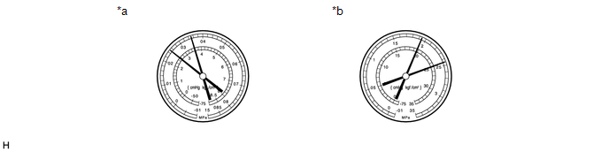 Text in Illustration
|
*a |
Low Pressure Side |
*b |
High Pressure Side |
|
Symptom |
Probable Cause |
Diagnosis |
Corrective Action |
|---|---|---|---|
|
Pressure extremely high on both low and high-pressure sides |
|
|
|
(7) The A/C system does not function due to air in the refrigeration system.
CAUTION:
The low-pressure piping may be very hot and cause serious burns.
NOTICE:
These gauge indications occur when the refrigeration system opens and the system is charged with refrigerant without vacuum purging.
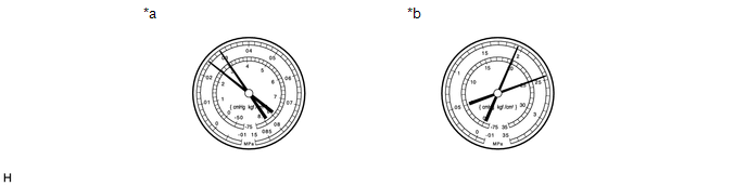 Text in Illustration
|
*a |
Low Pressure Side |
*b |
High Pressure Side |
|
Symptom |
Probable Cause |
Diagnosis |
Corrective Action |
|---|---|---|---|
|
Air in refrigeration system |
|
|
(8) The A/C system does not function effectively due to an expansion valve malfunction.
Text in Illustration
|
*a |
Low Pressure Side |
*b |
High Pressure Side |
|
Symptom |
Probable Cause |
Diagnosis |
Corrective Action |
|---|---|---|---|
|
Problem with expansion valve |
|
Replace expansion valve |
(9) The A/C system does not function due to a defective compressor.
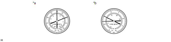 Text in Illustration
|
*a |
Low Pressure Side |
*b |
High Pressure Side |
|
Symptom |
Probable Cause |
Diagnosis |
Corrective Action |
|---|---|---|---|
|
Internal leakage in compressor |
|
Repair or replace compressor |

 Precaution
PRECAUTION
1. PRECAUTIONS FOR REFRIGERANT HFO-1234yf (R1234yf)
(a) Compatibility
(1) The parts used in the refrigerant cycle, the compressor oil, etc. of the
HFO-1234yf (R1234yf) system are not c ...
Other materials:
Data Signal Circuit between Radio Receiver and Stereo Jack Adapter
DESCRIPTION
The No. 1 stereo jack adapter assembly sends the sound data signal or image data
signal from a USB device to the radio and display receiver assembly via this circuit.
WIRING DIAGRAM
PROCEDURE
1.
CHECK HARNESS AND CONNECTOR (RADIO AND DISPLAY RECEIVER ASSEMB ...
Rear Door(for Double Cab)
Components
COMPONENTS
ILLUSTRATION
ILLUSTRATION
ILLUSTRATION
ILLUSTRATION
ILLUSTRATION
Adjustment
ADJUSTMENT
CAUTION / NOTICE / HINT
HINT:
Use the same procedures for both the LH and RH sides.
The procedure described below is for the LH side.
Centering bolts ...
Engine does not Start because No Initial Combustion
DESCRIPTION
When a key is inserted into the ignition key cylinder, the transponder
key coil receives the key ID code and sends it to the transponder key ECU
assembly.
If an error in communication between the transponder key coil and transponder
key ECU assembly occurs, this s ...
