Toyota Tacoma (2015-2018) Service Manual: Installation
INSTALLATION
PROCEDURE
1. SET NO. 1 CYLINDER TO TDC/COMPRESSION
.gif)
2. INSTALL CAMSHAFT TIMING GEAR BOLT
NOTICE:
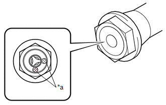
There are different types of camshaft timing gear bolts. Make sure to check the identification mark to determine the tightening torque.
|
*a |
Identification Mark Stamp |
|
Item |
Identification Mark Stamp |
|
|---|---|---|
|
Intake Side |
Exhaust Side |
|
|
Type A |
A |
B |
|
Type B |
D |
G |
|
(a) Apply engine oil to the areas of the camshaft timing gear bolt shown in the illustration. |
|
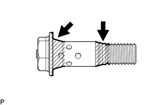
(b) Temporarily install the camshaft timing gear bolt.
Torque:
10 N·m {102 kgf·cm, 7 ft·lbf}
HINT:
Make sure that the flange part of the camshaft timing gear bolt is directly contacting the camshaft timing gear assembly.
(c) Loosen the camshaft timing gear bolt 60 to 180°.
|
(d) Using SST, hold the crankshaft pulley assembly. SST: 09213-54015 91651-60855 SST: 09330-00021 |
|
.png)
(e) Tighten the camshaft timing gear bolt.
Torque:
for Type A :
120 N·m {1224 kgf·cm, 89 ft·lbf}
for Type B :
95 N·m {969 kgf·cm, 70 ft·lbf}
3. INSTALL CAMSHAFT TIMING OIL CONTROL SOLENOID ASSEMBLY
(See page )
4. INSTALL NO. 1 ENGINE UNDER COVER SUB-ASSEMBLY
Torque:
30 N·m {306 kgf·cm, 22 ft·lbf}
5. INSTALL NO. 2 ENGINE UNDER COVER SUB-ASSEMBLY (w/ Off Road Package)
Torque:
30 N·m {306 kgf·cm, 22 ft·lbf}
 Removal
REMOVAL
CAUTION / NOTICE / HINT
NOTICE:
If one of the camshaft timing gear bolts is already removed, do not remove any
other camshaft timing gear bolts.
PROCEDURE
1. REMOVE NO. 2 ENGINE UNDER C ...

Other materials:
Ptc Heater Relay
Components
COMPONENTS
ILLUSTRATION
Inspection
INSPECTION
PROCEDURE
1. INSPECT PTC HEATER RELAY
(a) Check the resistance.
(1) Measure the resistance according to the value(s) in the table below.
Standard Resistance:
Tester Connection
C ...
Additional Key cannot be Registered
DESCRIPTION
If additional registration is not possible, a malfunction in the certification
ECU (smart key ECU assembly), engine switch, electrical key transmitter sub-assembly
or steering lock ECU (steering lock actuator or UPR bracket assembly) is suspected.
CAUTION / NOTICE / HINT
NOTICE ...
Vehicle Speed Tolerance Malfunction (C1AA2)
DESCRIPTION
The forward recognition camera receives vehicle speed tolerance signals from
the combination meter assembly. If the combination meter assembly detects a vehicle
speed tolerance malfunction signal, it informs the forward recognition camera via
CAN communication, and DTC C1AA2 is st ...
