Toyota Tacoma (2015-2018) Service Manual: Installation
INSTALLATION
PROCEDURE
1. INSTALL REAR SEATBACK HINGE SUB-ASSEMBLY
(a) Install the rear seatback hinge sub-assembly with the 2 bolts.
Torque:
30 N·m {306 kgf·cm, 22 ft·lbf}
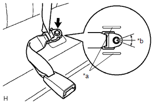
2. INSTALL REAR SEATBACK ASSEMBLY
(a) Install the rear seatback assembly with the 2 bolts.
Torque:
37 N·m {377 kgf·cm, 27 ft·lbf}
|
(b) Connect the rear seat inner belt assembly and rear center seat outer belt assembly by installing the floor anchor with the bolt. Text in Illustration
Torque: 42 N·m {428 kgf·cm, 31 ft·lbf} NOTICE:
|
|
3. INSTALL REAR SEATBACK HINGE COVER
(a) Engage the 6 claws to install the 2 rear seatback hinge covers.
4. INSTALL REAR SEAT CUSHION ASSEMBLY
(a) Install the rear seat cushion with the 2 bolts.
Torque:
37 N·m {377 kgf·cm, 27 ft·lbf}
 Removal
REMOVAL
PROCEDURE
1. REMOVE REAR SEAT CUSHION ASSEMBLY
(a) Remove the 2 bolts and rear seat cushion assembly.
2. REMOVE REAR SEATBACK HINGE COV ...
 Reassembly
REASSEMBLY
CAUTION / NOTICE / HINT
CAUTION:
Wear protective gloves. Sharp areas on the parts may injure your hands.
PROCEDURE
1. INSTALL SEPARATE TYPE REAR SEATBACK COVER
(a) Using ho ...
Other materials:
Air Inlet Control Servo Motor
Inspection
INSPECTION
PROCEDURE
1. INSPECT AIR INLET CONTROL SERVO MOTOR
(a) Inspect the servo motor operation.
(1) Connect the positive (+) lead from the battery to terminal 1 (FRS)
and negative (-) lead to terminals 2 (REC), then check that the shaft rotates
clockwise s ...
System Diagram
SYSTEM DIAGRAM
Communication Table
Sender
Receiver
Signal
Communication Method
Airbag sensor assembly
Main body ECU
Front seat inner belt assembly LH buckle switch
CAN
Combination mete ...
Precaution
PRECAUTION
1. EXPRESSIONS OF IGNITION SWITCH
HINT:
The type of ignition switch used on this model differs according to the specifications
of the vehicle. The expressions listed in the table below are used in this section.
Expression
Ignition Switch
(Position)
...
