Toyota Tacoma (2015-2018) Service Manual: Reassembly
REASSEMBLY
CAUTION / NOTICE / HINT
HINT:
- Use the same procedure for the RH side and LH side.
- The following procedure is for the LH side.
- When installing a new front wheel opening extension pad or No. 1 front wheel opening extension pad or No. 2 front wheel opening extension pad, heat the front fender wheel opening moulding using a heat light.
- When installing a new No. 1 body outside moulding pad or No. 2 body outside moulding pad or No. 3 body outside moulding pad, heat the quarter panel wheel opening moulding using a heat light.
|
Item |
Temperature |
|---|---|
|
Front Fender Wheel Opening Moulding or Quarter Panel Wheel Opening Moulding |
20 to 30┬░C (68 to 86┬░F) |
NOTICE:
Do not heat the front fender wheel opening moulding or quarter panel wheel opening moulding excessively.
PROCEDURE
1. INSTALL NO. 1 BODY OUTSIDE MOULDING PAD
(a) Clean the quarter panel wheel opening moulding.
(1) Using a heat light, heat the quarter panel wheel opening moulding surface.
(2) Remove the double-sided tape from the quarter panel wheel opening moulding.
(3) Clean off any tape adhesive residue with cleaner.
(b) Install a new No. 1 body outside moulding pad.
(1) Using a heat light, heat the quarter panel wheel opening moulding.
(2) Remove the release paper from the No. 1 body outside moulding pad.
HINT:
After removing the release paper, keep the exposed adhesive free from foreign matter.
|
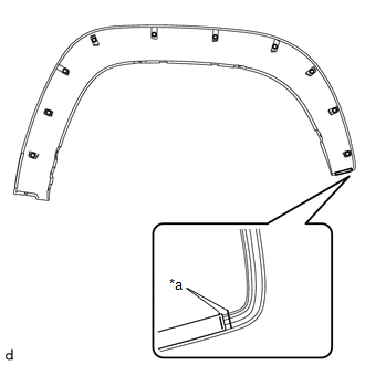
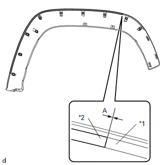
(3) Install the No. 1 body outside moulding pad as shown in the illustration. HINT: Make sure to install the No. 1 body outside moulding pad so that the ends of the No. 1 body outside moulding pad are within each area shown in the illustration. |
|
2. INSTALL NO. 2 BODY OUTSIDE MOULDING PAD
(a) Clean the quarter panel wheel opening moulding.
(1) Using a heat light, heat the quarter panel wheel opening moulding surface.
(2) Remove the double-sided tape from the quarter panel wheel opening moulding.
(3) Clean off any tape adhesive residue with cleaner.
(b) Install a new No. 2 body outside moulding pad.
(1) Using a heat light, heat the quarter panel wheel opening moulding.
(2) Remove the release paper from the No. 2 body outside moulding pad.
HINT:
After removing the release paper, keep the exposed adhesive free from foreign matter.
|
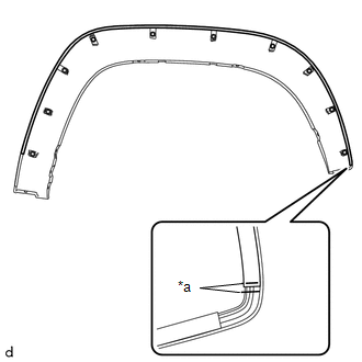
(3) Install the No. 2 body outside moulding pad as shown in the illustration. HINT: Make sure to install the No. 2 body outside moulding pad so that the ends of the No. 2 body outside moulding pad are within each area shown in the illustration. |
|
3. INSTALL NO. 3 BODY OUTSIDE MOULDING PAD
(a) Clean the quarter panel wheel opening moulding.
(1) Using a heat light, heat the quarter panel wheel opening moulding surface.
(2) Remove the double-sided tape from the quarter panel wheel opening moulding.
(3) Clean off any tape adhesive residue with cleaner.
(b) Install a new No. 3 body outside moulding pad.
(1) Using a heat light, heat the quarter panel wheel opening moulding.
(2) Remove the release paper from the No. 3 body outside moulding pad.
HINT:
After removing the release paper, keep the exposed adhesive free from foreign matter.
|
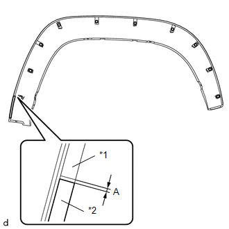
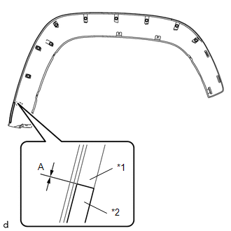
(3) Install the No. 3 body outside moulding pad as shown in the illustration. Standard Measurement:
|
|
4. INSTALL FRONT WHEEL OPENING EXTENSION PAD
(a) Clean the front fender wheel opening moulding.
(1) Using a heat light, heat the front fender wheel opening moulding surface.
(2) Remove the double-sided tape from the front fender wheel opening moulding.
(3) Clean off any tape adhesive residue with cleaner.
(b) Install a new front wheel opening extension pad.
(1) Using a heat light, heat the front fender wheel opening moulding.
(2) Remove the release paper from the front wheel opening extension pad.
HINT:
After removing the release paper, keep the exposed adhesive free from foreign matter.
|
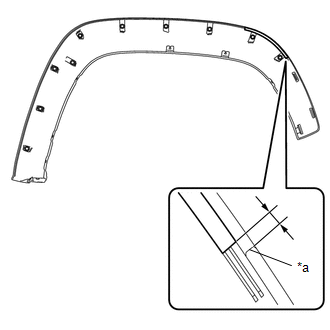
(3) Install the front wheel opening extension pad as shown in the illustration. HINT: Make sure to install the front wheel opening extension pad so that the ends of the front wheel opening extension pad are within each area shown in the illustration. Standard Measurement:
|
|
5. INSTALL NO. 1 FRONT WHEEL OPENING EXTENSION PAD
(a) Clean the front fender wheel opening moulding.
(1) Using a heat light, heat the front fender wheel opening moulding surface.
(2) Remove the double-sided tape from the front fender wheel opening moulding.
(3) Clean off any tape adhesive residue with cleaner.
(b) Install a new No. 1 front wheel opening extension pad.
(1) Using a heat light, heat the front fender wheel opening moulding.
(2) Remove the release paper from the No. 1 front wheel opening extension pad.
HINT:
After removing the release paper, keep the exposed adhesive free from foreign matter.
|
(3) Install the No. 1 front wheel opening extension pad as shown in the illustration. Standard Measurement:
|
|
6. INSTALL NO. 2 FRONT WHEEL OPENING EXTENSION PAD
(a) Clean the front fender wheel opening moulding.
(1) Using a heat light, heat the front fender wheel opening moulding surface.
(2) Remove the double-sided tape from the front fender wheel opening moulding.
(3) Clean off any tape adhesive residue with cleaner.
(b) Install a new No. 2 front wheel opening extension pad.
(1) Using a heat light, heat the front fender wheel opening moulding.
(2) Remove the release paper from the No. 2 front wheel opening extension pad.
HINT:
After removing the release paper, keep the exposed adhesive free from foreign matter.
|
(3) Install the No. 2 front wheel opening extension pad as shown in the illustration. Standard Measurement:
|
|
 Disassembly
DISASSEMBLY
CAUTION / NOTICE / HINT
HINT:
Use the same procedure for the RH side and LH side.
The following procedure is for the LH side.
When removing the No. 2 front wheel opening ...
 Removal
REMOVAL
CAUTION / NOTICE / HINT
HINT:
Use the same procedure for the RH side and LH side.
The following procedure is for the LH side.
When removing the front fender wheel opening mo ...
Other materials:
Lost Communication with ECM / PCM "A" (U0100,U0122)
DESCRIPTION
This DTC is output when communication is lost with the skid control ECU (brake
actuator assembly) or ECM.
DTC No.
Detection Item
DTC Detection Condition
Trouble Area
U0100
Lost Communication with ECM / PCM " ...
System Diagram
SYSTEM DIAGRAM
This is a detailed diagram related to the main body ECU (multiplex network body
ECU).
Component
Function
Front door outside handle assembly LH
Receives request signals from the certification ECU (smart key ECU assembly) ...
Tires
Replace or rotate tires in accordance with maintenance schedules and treadwear.
■ Checking tire
1. New tread
2. Treadwear indicator
3. Worn tread
The location of treadwear indicators is shown by the тАЬTWIтАЭ or тАЬ
тАЭ marks, etc., molded on the sidewall of each tire.
Check spare ti ...
