Toyota Tacoma (2015-2018) Service Manual: Oil Pressure Switch
Components
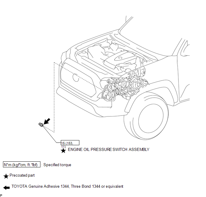
COMPONENTS
ILLUSTRATION
Removal
REMOVAL
PROCEDURE
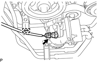
1. REMOVE ENGINE OIL PRESSURE SWITCH ASSEMBLY
|
(a) Disengage the clamp and disconnect the engine oil pressure switch connector. |
|
|
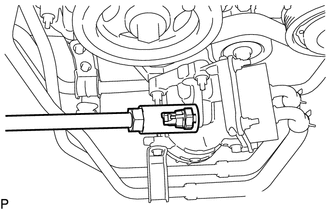
(b) Using a 24 mm deep socket wrench, remove the engine oil pressure switch assembly. |
|
Inspection
INSPECTION
PROCEDURE
1. INSPECT ENGINE OIL PRESSURE SWITCH ASSEMBLY
(a) Disconnect the engine oil pressure switch connector.
(b) Start the engine.
(c) Measure the resistance according to the value(s) in the table below.
Standard Resistance:
|
Tester Connection |
Condition |
Specified Condition |
|---|---|---|
|
1 - Body ground |
Engine stopped |
Below 1 Ω |
|
Engine idling |
10 kΩ or higher |
If the result is not as specified, replace the engine oil pressure switch assembly.
(d) Connect the engine oil pressure switch connector.
Installation
INSTALLATION
PROCEDURE
1. INSTALL ENGINE OIL PRESSURE SWITCH ASSEMBLY
(a) Apply adhesive to 2 or 3 threads of the engine oil pressure switch assembly.
Adhesive:
Toyota Genuine Adhesive 1344, Three Bond 1344 or equivalent
NOTICE:
Do not apply adhesive to the oil inlet port of the engine oil pressure switch assembly.
(b) Using a 24 mm deep socket wrench, install the engine oil pressure switch assembly.
Torque:
15 N·m {153 kgf·cm, 11 ft·lbf}
NOTICE:
Do not start the engine within 1 hour of installation.
(c) Connect the engine oil pressure switch connector and attach the clamp.
2. INSPECT FOR ENGINE OIL LEAK
.gif)
3. INSPECT ENGINE OIL LEVEL
 Oil Level Sensor
Components
COMPONENTS
ILLUSTRATION
ILLUSTRATION
Inspection
INSPECTION
PROCEDURE
1. INSPECT ENGINE OIL LEVEL SENSOR
(a) Measure the resistance according to the value(s) in th ...
 Oil Pump
...
Other materials:
VSC Buzzer Circuit
DESCRIPTION
The skid control ECU (brake actuator assembly) is connected to the combination
meter via CAN communication.
The combination meter has a built-in VSC warning buzzer:
Sounds intermittently to inform the driver if the temperature of brake
actuator assembly has increased exce ...
Installation
INSTALLATION
PROCEDURE
1. INSTALL OIL COOLER TUBE
(a) Install the oil cooler tube to the vehicle body with the 2 bolts.
Torque:
28 N·m {286 kgf·cm, 21 ft·lbf}
2. INSTALL NO. 4 OIL COOLER INLET HOSE AND NO. 4 OIL COOLER OUTLET HOSE
NOTICE:
When connecting the hoses to the tube, su ...
Front Radar Sensor Region Code Mismatch (C1A0A)
DESCRIPTION
When the destination information in the millimeter wave radar sensor assembly
and forward recognition camera do not match, DTC C1A0A is stored.
DTC No.
Detection Item
DTC Detection Condition
Trouble Area
MIL
C1A0 ...
