Toyota Tacoma (2015-2018) Service Manual: Oil Level Sensor
Components
COMPONENTS
ILLUSTRATION
ILLUSTRATION
Inspection
INSPECTION
PROCEDURE
1. INSPECT ENGINE OIL LEVEL SENSOR
|
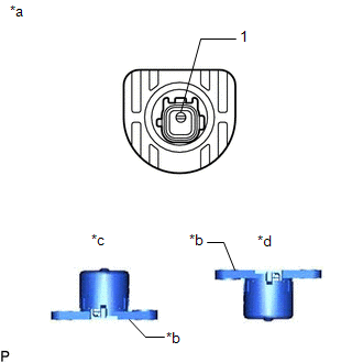
(a) Measure the resistance according to the value(s) in the table below. Standard Resistance:
If the result is not as specified, replace the engine oil level sensor. |
|
Installation
INSTALLATION
PROCEDURE
1. INSTALL ENGINE OIL LEVEL SENSOR
(a) Apply a light coat of engine oil to the O-ring of the engine oil level sensor.
|
(b) Install a new clip to the engine oil level sensor as shown in the illustration. |
|

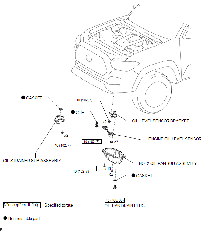
(c) Install the oil level sensor bracket with the 2 nuts.
Torque:
10 N·m {102 kgf·cm, 7 ft·lbf}
(d) Install the engine oil level sensor with the 2 nuts.
Torque:
10 N·m {102 kgf·cm, 7 ft·lbf}
(e) Engage the clamp and disconnect the engine oil level sensor connector.
2. INSTALL OIL STRAINER SUB-ASSEMBLY
.gif)
3. INSTALL NO. 2 OIL PAN SUB-ASSEMBLY
4. ADD ENGINE OIL
5. INSPECT FOR OIL LEAK
6. INSPECT ENGINE OIL LEVEL
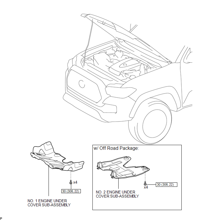
7. INSTALL NO. 1 ENGINE UNDER COVER SUB-ASSEMBLY
8. INSTALL NO. 2 ENGINE UNDER COVER SUB-ASSEMBLY (w/ Off Road Package)
Removal
REMOVAL
PROCEDURE
1. REMOVE NO. 2 ENGINE UNDER COVER SUB-ASSEMBLY (w/ Off Road Package)
2. REMOVE NO. 1 ENGINE UNDER COVER SUB-ASSEMBLY
3. DRAIN ENGINE OIL
.gif)
4. REMOVE NO. 2 OIL PAN SUB-ASSEMBLY
5. REMOVE OIL STRAINER SUB-ASSEMBLY
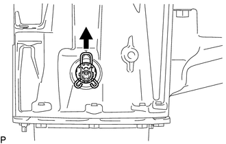
6. REMOVE ENGINE OIL LEVEL SENSOR
|
(a) Disengage the clamp and disconnect the engine oil level sensor connector. |
|
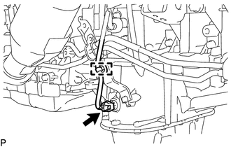
|
(b) Remove the clip from the engine oil level sensor. |
|
|
(c) Remove the 2 nuts from the engine oil level sensor. |
|
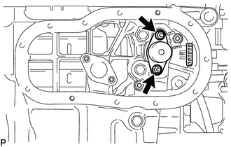
|
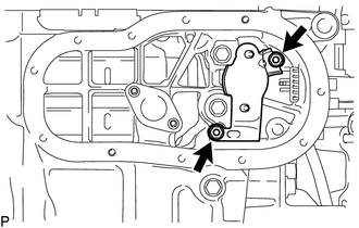
(d) Remove the 2 nuts and oil level sensor bracket. |
|
(e) Remove the engine oil level sensor.
 Replacement
REPLACEMENT
CAUTION / NOTICE / HINT
CAUTION:
Prolonged and repeated contact with engine oil will result in the removal
of natural oils from the skin, leading to dryness, irritation and ...
 Oil Pressure Switch
Components
COMPONENTS
ILLUSTRATION
Removal
REMOVAL
PROCEDURE
1. REMOVE ENGINE OIL PRESSURE SWITCH ASSEMBLY
(a) Disengage the clamp and disconnect the engine oil pressure switch ...
Other materials:
Operation Check
OPERATION CHECK
1. CHECK REMOTE CONTROL MIRROR FUNCTION
(a) Turn the ignition switch to ON.
(b) With L on the mirror select switch selected, check that the outer rear view
mirror assembly LH surface moves up, down, left and right normally.
(c) With R on the mirror select switch selected, check ...
PTC Heater Circuit
DESCRIPTION
PTC HTR heater relays are closed in accordance with signals from the air conditioning
amplifier assembly and power is supplied to the quick heater assembly installed
on the radiator heater unit.
WIRING DIAGRAM
CAUTION / NOTICE / HINT
NOTICE:
Inspect the fuses for circuits rela ...
Installation
INSTALLATION
CAUTION / NOTICE / HINT
HINT:
Use the same procedure for the RH and LH sides.
The procedure listed below is for the LH side.
PROCEDURE
1. INSTALL FRONT NO. 1 SPEAKER ASSEMBLY
(a) Install the front No. 1 speaker assembly with the 4 screws.
NOTICE:
Do not touch t ...
