Toyota Tacoma (2015-2018) Service Manual: Neutral Position Switch
Components
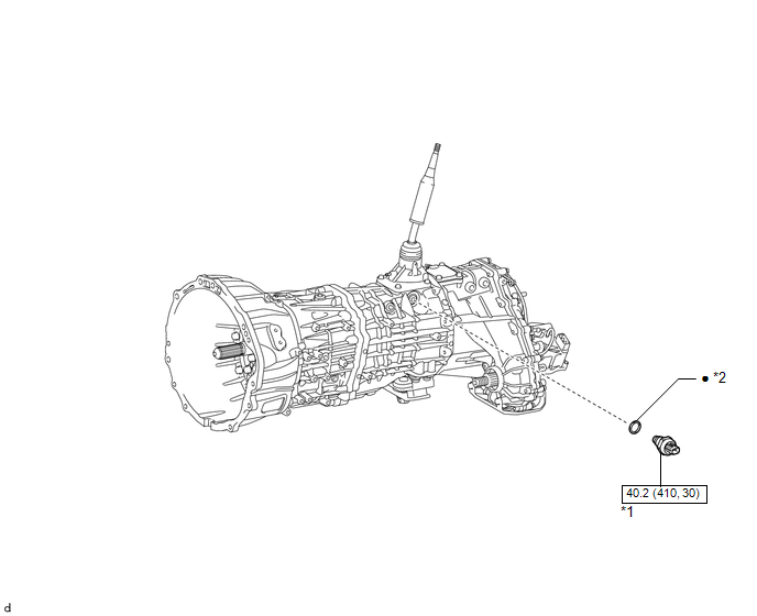
COMPONENTS
ILLUSTRATION
|
*1 |
NEUTRAL POSITION SWITCH |
*2 |
GASKET |
.png) |
N*m (kgf*cm, ft.*lbf): Specified torque |
â—Ź |
Non-reusable part |
Installation
INSTALLATION
PROCEDURE
1. INSTALL NEUTRAL POSITION SWITCH
|
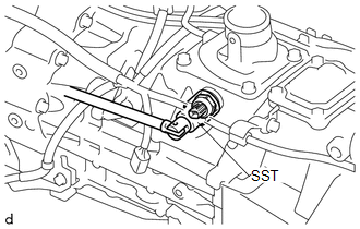
(a) Using SST, install the neutral position switch and a new gasket to the transmission case. SST: 09817-16011 Torque: 40.2 N·m {410 kgf·cm, 30 ft·lbf} |
|
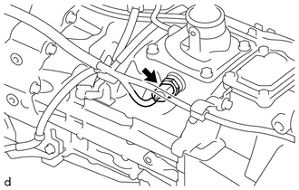
(b) Connect the connector.
Removal
REMOVAL
PROCEDURE
1. REMOVE NEUTRAL POSITION SWITCH
|
(a) Disconnect the connector. |
|
|
(b) Using SST, remove the neutral position switch and gasket from the transmission case. SST: 09817-16011 |
|
.png)
 Manual Transmission Unit
Components
COMPONENTS
ILLUSTRATION
ILLUSTRATION
*1
SHIFT DETENT BALL PLUG
*2
SHIFT DETENT BALL COMPRESSION SPRING
*3
M ...
 Output Shaft
Components
COMPONENTS
ILLUSTRATION
Disassembly
DISASSEMBLY
PROCEDURE
1. REMOVE FRONT OUTPUT SHAFT BEARING
(a) Temporarily install the manual transmission output shaft rear set ...
Other materials:
Cruise control
Use the cruise control to maintain a set speed without depressing the accelerator
pedal.
Indicator
Cruise control switch
■ Setting the vehicle speed
Press the ON-OFF button to activate the cruise control.
Cruise control indicator will come on.
Press the button again to deactivate ...
How To Proceed With Troubleshooting
CAUTION / NOTICE / HINT
HINT:
Use these procedures to troubleshoot the smart key system (for Start
Function).
*: Use the Techstream.
PROCEDURE
1.
VEHICLE BROUGHT TO WORKSHOP
NEXT
...
Control Module Communication Bus OFF (U0073,U0100,U0114,U0123,U0124,U0126)
DESCRIPTION
The skid control ECU (master cylinder solenoid) receives the signals from the
ECM, steering angle sensor (spiral cable with sensor sub-assembly), 4 wheel drive
control ECU*, and yaw rate and acceleration sensor (airbag sensor assembly) via
the CAN communication system.
*: ...
