Toyota Tacoma (2015-2018) Service Manual: Reassembly
REASSEMBLY
CAUTION / NOTICE / HINT
HINT:
- Use the same procedure for both the LH and RH sides.
- The procedure described below is for the LH side.
PROCEDURE
1. INSTALL CLEARANCE LIGHT BULB
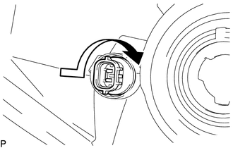
(a) Install the clearance light bulb to the clearance light socket.
|
(b) Turn the clearance light socket with clearance light bulb in the direction indicated by the arrow shown in the illustration to install them. |
|
2. INSTALL FRONT TURN SIGNAL LIGHT BULB
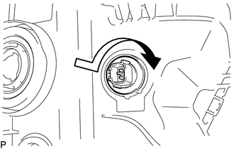
(a) Install the front turn signal light bulb to the front turn signal light socket.
|
(b) Turn the front turn signal light socket with front turn signal light bulb in the direction indicated by the arrow shown in the illustration to install them. |
|
3. INSTALL NO. 2 HEADLIGHT BULB
|
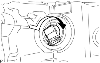
(a) Turn the No. 2 headlight bulb in the direction indicated by the arrow in the illustration to install it. NOTICE: Do not touch the No. 2 headlight bulb glass. |
|
4. INSTALL NO. 1 HEADLIGHT BULB
|
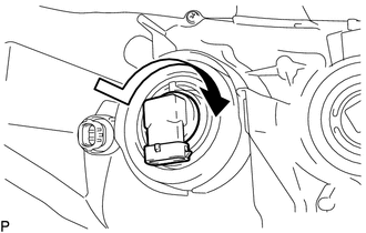
(a) Turn the No. 1 headlight bulb in the direction indicated by the arrow in the illustration to install it. NOTICE: Do not touch the No. 1 headlight bulb glass. |
|
 Installation
INSTALLATION
CAUTION / NOTICE / HINT
HINT:
Use the same procedure for both the LH and RH sides.
The procedure described below is for the LH side.
PROCEDURE
1. INSTALL HEADLIGHT ...
 Headlight Dimmer Relay
Inspection
INSPECTION
PROCEDURE
1. INSPECT HEADLIGHT DIMMER RELAY
(a) Check the resistance.
(1) Measure the resistance according to the value(s) in the table below.
Standard:
...
Other materials:
Invalid Data Received from Deceleration Sensor (C1442,C1443)
DESCRIPTION
The airbag sensor assembly has a built-in yaw rate and acceleration sensor.
The skid control ECU (brake actuator assembly) receives signals from the yaw
rate and acceleration sensor (airbag sensor assembly) via the CAN communication
system.
DTC No.
Detection ...
Operation Check
OPERATION CHECK
1. BLIND SPOT MONITOR BEAM AXIS INSPECTION
(a) Procedure to enter Test Mode
(1) Connect the Techstream to the DLC3.
(2) Turn the ignition switch to ON.
(3) Turn the blind spot monitor main switch assembly (warning canceling switch
assembly) on.
(4) Turn the Techstream on.
(5 ...
Transmission Range Sensor "A" Circuit Open (P070513,P070562)
DESCRIPTION
The park/neutral position switch detects the shift lever position and sends signals
to the ECM.
DTC No.
DTC Detection Condition
Trouble Area
SAE
P070513
All of the following signals are OFF simultaneously for 60 ...
