Toyota Tacoma (2015-2018) Service Manual: Navigation Antenna
Components
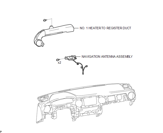
COMPONENTS
ILLUSTRATION
Installation
INSTALLATION
PROCEDURE
1. INSTALL NAVIGATION ANTENNA ASSEMBLY
(a) Install the navigation antenna assembly with the 2 screws.
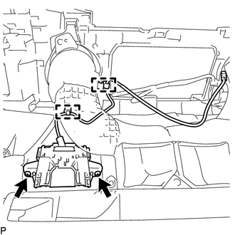
(b) Engage the 2 clamps.
2. INSTALL NO. 1 HEATER TO REGISTER DUCT
(See page .gif) )
)
3. INSTALL INSTRUMENT PANEL SUB-ASSEMBLY
(See page )
Removal
REMOVAL
PROCEDURE
1. REMOVE INSTRUMENT PANEL SUB-ASSEMBLY
(See page .gif) )
)
2. REMOVE NO. 1 HEATER TO REGISTER DUCT
(See page )
3. REMOVE NAVIGATION ANTENNA ASSEMBLY
|
(a) Disengage the 2 clamps. |
|
(b) Remove the 2 screws and navigation antenna assembly.

 Navigation Receiver
Components
COMPONENTS
ILLUSTRATION
ILLUSTRATION
Removal
REMOVAL
PROCEDURE
1. REMOVE INSTRUMENT CLUSTER CENTER FINISH PANEL SUB-ASSEMBLY
(See page )
2. REMOVE NAVIGATION RECEIVER ASS ...
Other materials:
Installation
INSTALLATION
PROCEDURE
1. INSTALL INSTRUMENT PANEL PASSENGER AIRBAG ASSEMBLY WITHOUT DOOR
(a) Engage the 3 hooks (B).
Text in Illustration
*a
Hooks (A)
*b
Hooks (B)
...
System Description
SYSTEM DESCRIPTION
1. GENERAL
(a) The air conditioning system has the following controls.
Control
Outline
Manual Control
The air conditioner amplifier assembly controls the damper positions
(air inlet control damper, air mix control damper and ...
Air Conditioning Compressor Magnetic Clutch Circuit
DESCRIPTION
When the air conditioning amplifier assembly is turned on, a magnetic clutch
on signal is sent from the MGC terminal of the air conditioning amplifier assembly.
Then, the MG CLT relay turns on to operate the magnetic clutch assembly.
WIRING DIAGRAM
CAUTION / NOTICE / HINT
NO ...
