INSTALLATION
PROCEDURE
1. INSTALL INSTRUMENT PANEL PASSENGER AIRBAG ASSEMBLY WITHOUT DOOR
|
(a) Engage the 3 hooks (B). Text in Illustration
|
|
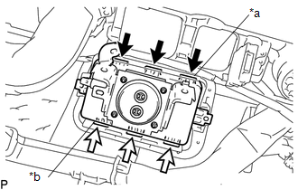
(b) Engage the 3 hooks (A) to install the instrument panel passenger airbag assembly without door on the instrument panel.
(c) Install the 2 screws.
2. INSTALL INSTRUMENT PANEL WIRE ASSEMBLY
(a) Engage the 2 clamps to install the instrument panel wire assembly.
|
(b) Connect the 3 airbag connectors. NOTICE: When handling the airbag connector, take care not to damage the airbag wire harness. |
|
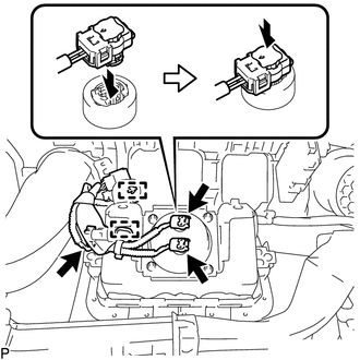
(c) Push in the 3 airbag connector locks to install the 3 airbag connectors.
3. INSTALL NO.3 HEATER TO REGISTER DUCT
4. INSTALL INSTRUMENT PANEL SUB-ASSEMBLY
5. INSPECT SRS WARNING LIGHT
(See page
)
Components
On-vehicle InspectionDriver Side Door Entry Lock Function does not Operate
DESCRIPTION
If the entry lock function does not operate for the driver door only, but the
entry unlock function operates, the request code is being transmitted properly from
the driver door. In this case, there may be a problem related to the front door
outside handle assembly LH (lock sensor ...
Terminals Of Ecu
TERMINALS OF ECU
1. CHECK DRIVER SIDE JUNCTION BLOCK AND MAIN BODY ECU (MULTIPLEX NETWORK BODY
ECU)
(a) Disconnect the MB main body ECU (multiplex network body ECU) connectors.
(b) Measure the voltage and resistance according to the value(s) in the table
below.
HINT:
Measure the values on ...
Open in Bus 3 Main Bus Line
DESCRIPTION
There may be an open circuit in one of the CAN main bus lines when the resistance
between terminals 6 (CA3H) and 21 (CA3L) of the central gateway ECU (network gateway
ECU) is 70 Ω or higher.
Detection Item
Trouble Area
Resistance between term ...