Toyota Tacoma (2015-2018) Service Manual: Navigation Receiver
Components
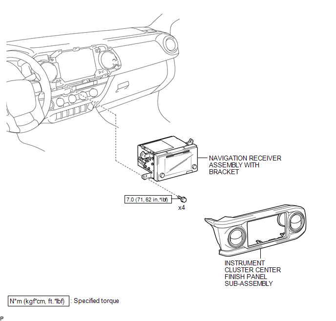
COMPONENTS
ILLUSTRATION
ILLUSTRATION
Removal
REMOVAL
PROCEDURE
1. REMOVE INSTRUMENT CLUSTER CENTER FINISH PANEL SUB-ASSEMBLY
(See page .gif) )
)
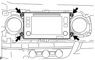
2. REMOVE NAVIGATION RECEIVER ASSEMBLY WITH BRACKET
|
(a) Remove the 4 bolts. |
|
(b) Disconnect the connectors to remove the navigation receiver assembly with bracket.
3. REMOVE NO. 1 NAVIGATION WIRE (w/ Satellite Radio)
(See page )
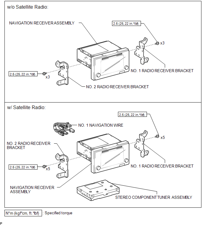
4. REMOVE NO. 1 RADIO RECEIVER BRACKET
 Text in Illustration
|
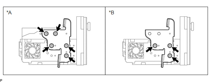
*A |
w/ Satellite Radio |
*B |
w/o Satellite Radio |
(a) w/ Satellite Radio:
Remove the 5 bolts and No. 1 radio receiver bracket.
(b) w/o Satellite Radio:
Remove the 3 bolts and No. 1 radio receiver bracket.
5. REMOVE NO. 2 RADIO RECEIVER BRACKET
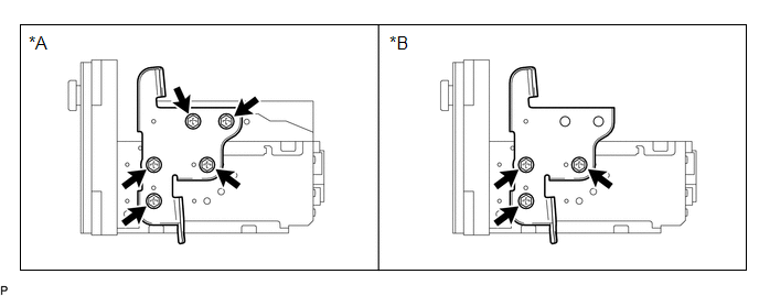 Text in Illustration
|
*A |
w/ Satellite Radio |
*B |
w/o Satellite Radio |
(a) w/ Satellite Radio:
Remove the 5 bolts and No. 2 radio receiver bracket.
(b) w/o Satellite Radio:
Remove the 3 bolts and No. 2 radio receiver bracket.
6. REMOVE STEREO COMPONENT TUNER ASSEMBLY (w/ Satellite Radio)
(See page )
Installation
INSTALLATION
PROCEDURE
1. INSTALL STEREO COMPONENT TUNER ASSEMBLY (w/ Satellite Radio)
(See page .gif) )
)
2. INSTALL NO. 2 RADIO RECEIVER BRACKET
(a) w/o Satellite Radio:
Install the No. 2 radio receiver bracket with the 3 bolts.
Torque:
2.5 N·m {25 kgf·cm, 22 in·lbf}
(b) w/ Satellite Radio:
Install the No. 2 radio receiver bracket with the 5 bolts.
Torque:
2.5 N·m {25 kgf·cm, 22 in·lbf}
3. INSTALL NO. 1 RADIO RECEIVER BRACKET
(a) w/o Satellite Radio:
Install the No. 1 radio receiver bracket with the 3 bolts.
Torque:
2.5 N·m {25 kgf·cm, 22 in·lbf}
(b) w/ Satellite Radio:
Install the No. 1 radio receiver bracket with the 5 bolts.
Torque:
2.5 N·m {25 kgf·cm, 22 in·lbf}
4. INSTALL NO. 1 NAVIGATION WIRE (w/ Satellite Radio)
(See page )
5. INSTALL NAVIGATION RECEIVER ASSEMBLY WITH BRACKET
(a) Connect the connectors.
(b) Install the navigation receiver assembly with bracket with the 4 bolts.
Torque:
7.0 N·m {71 kgf·cm, 62 in·lbf}
6. INSTALL INSTRUMENT CLUSTER CENTER FINISH PANEL SUB-ASSEMBLY
(See page )
 Navigation Antenna
Components
COMPONENTS
ILLUSTRATION
Installation
INSTALLATION
PROCEDURE
1. INSTALL NAVIGATION ANTENNA ASSEMBLY
(a) Install the navigation antenna assembly with the 2 screws.
(b) Engage th ...

Other materials:
Zero Point Calibration of Yaw Rate Sensor Undone (C1210,C1336)
DESCRIPTION
The skid control ECU (master cylinder solenoid) receives signals from the yaw
rate and acceleration (airbag sensor assembly) via the CAN communication system.
The airbag sensor assembly has a built-in yaw rate and acceleration sensor and
detects the vehicle's condition using 2 ...
Check Bus 5 Line for Short to GND
DESCRIPTION
There may be a short circuit between one of the CAN bus lines and GND when there
is no resistance between terminal 15 (CA5H) of the central gateway ECU (network
gateway ECU) and terminal 4 (CG) of the DLC3, or terminal 16 (CA5L) of the central
gateway ECU (network gateway ECU) and ...
Problem Symptoms Table
PROBLEM SYMPTOMS TABLE
HINT:
Use the table below to help determine the cause of problem symptoms.
If multiple suspected areas are listed, the potential causes of the symptoms
are listed in order of probability in the "Suspected Area" column of the
table. Check each sy ...
