Toyota Tacoma (2015-2018) Service Manual: System Description
SYSTEM DESCRIPTION
1. GENERAL
(a) The air conditioning system has the following controls.
|
Control |
Outline |
|---|---|
|
Manual Control |
The air conditioner amplifier assembly controls the damper positions (air inlet control damper, air mix control damper and mode control damper) and blower speed in accordance with the positions of the switches (temperature control dial, blower dial, mode select dial and air inlet control switch). |
|
Air Inlet Control |
Drives the air inlet servo motor (damper servo sub-assembly) according to the operation of the air inlet control switch and moves the dampers to the fresh or recirculation position. |
|
Compressor Control |
Controls the compressor with magnet clutch assembly to turn on or off based on the signals from various sensors. |
|
MAX Air Conditioning Control |
When the temperature control dial is turned to the MAX A/C position, the air conditioner amplifier assembly performs the following control to improve cooling efficiency:
|
|
Diagnosis |
A Diagnostic Trouble Code (DTC) is stored in the memory when the air conditioner amplifier assembly detects a problem with the air conditioning system. |
- *: for Double Cab
2. MODE POSITION AND DAMPER OPERATION
(a) Mode Position and Damper Operation
.png) Functions of Main Dampers
Functions of Main Dampers
|
Control Door |
Operation Position |
Door Position |
Operation |
|
|---|---|---|---|---|
|
Air Inlet Control Door |
FRESH |
A |
Brings in fresh air. |
|
|
RECIRCULATION |
B |
Recirculates internal air. |
||
|
Air Mix Control Door |
MAX COLD to MAX HOT Temperature Setting |
C - D - E (C' - D' - E') |
Varies the mixture ratio of warm air and cool air in order to regulate the temperature continuously between hot and cold. |
|
|
Mode Control Door |
.png) |
FACE |
F, J, N |
Air blows out of the front center register and side register. |
.png) |
BI-LEVEL |
G, L, N |
Air blows out of the front center register, side register and front and rear footwell register ducts*. |
|
.png) |
FOOT |
H, M, O |
Air blows out of the front and rear footwell register ducts*. In addition, air blows out slightly from the front and rear center register*, side register and defroster. |
|
.png) |
FOOT AND DEFROSTER |
H, M, P |
Defrosts the windshield through the center defroster, side defroster, side register, front and rear center register ducts*, while air is also blown out from the front and rear footwell register ducts*. |
|
.png) |
DEFROSTER |
I, J, Q |
Defrosts the windshield through the center defroster, side defroster. |
|
- *: for Double Cab
3. AIR OUTLETS AND AIRFLOW VOLUME
(a) Air Outlets and Airflow Volume
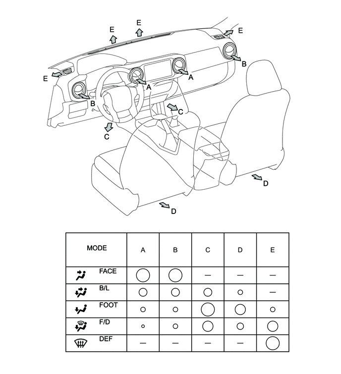
HINT:
The size of each circle â—‹ indicates the ratio of airflow volume.
 How To Proceed With Troubleshooting
CAUTION / NOTICE / HINT
HINT:
Use the following procedure to troubleshoot the air conditioning system.
*: Use the Techstream.
PROCEDURE
1.
VEHICLE BROUG ...
 System Diagram
SYSTEM DIAGRAM
...
Other materials:
Differential Oil
Adjustment
ADJUSTMENT
PROCEDURE
1. INSPECT DIFFERENTIAL OIL
(a) Stop the vehicle on a level place.
(b) Remove the differential filler plug and gasket.
(c) Check that the oil level is within 5 mm (0 to 0.20 in.) of the bottom of
the filler plug opening.
NOTICE:
Excessively large ...
Event data recorder
This vehicle is equipped with an event data recorder (EDR). The main purpose
of an EDR is to record, in certain crash or near crash-like situations, such as
an air bag deployment or hitting a road obstacle, data that will assist in understanding
how a vehicle’s systems performed. The EDR is ...
Installation
INSTALLATION
PROCEDURE
1. INSTALL OIL COOLER TUBE
(a) Install the oil cooler tube to the vehicle body with the 2 bolts.
Torque:
28 N·m {286 kgf·cm, 21 ft·lbf}
2. INSTALL NO. 4 OIL COOLER INLET HOSE AND NO. 4 OIL COOLER OUTLET HOSE
NOTICE:
When connecting the hoses to the tube, su ...
