Toyota Tacoma (2015-2018) Service Manual: Parts Location
PARTS LOCATION
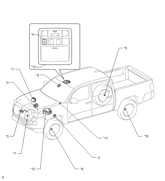
ILLUSTRATION
|
*1 |
SKID CONTROL ECU (BRAKE ACTUATOR ASSEMBLY) |
*2 |
THROTTLE BODY WITH MOTOR ASSEMBLY |
|
*3 |
PARK/NEUTRAL POSITION SWITCH |
*4 |
VSC OFF SWITCH |
|
*5 |
MILLIMETER WAVE RADAR SENSOR ASSEMBLY |
*6 |
FORWARD RECOGNITION CAMERA |
|
*7 |
FRONT SPEED SENSOR RH |
*8 |
FRONT SPEED SENSOR LH |
|
*9 |
REAR SPEED SENSOR RH |
*10 |
REAR SPEED SENSOR LH |
|
*11 |
SKID CONTROL BUZZER |
*12 |
ENGINE ROOM RELAY BLOCK - IG2 FUSE - STOP FUSE - STOP RELAY |
|
*13 |
ROOF CONSOLE BOX ASSEMBLY |
- |
- |
ILLUSTRATION
|
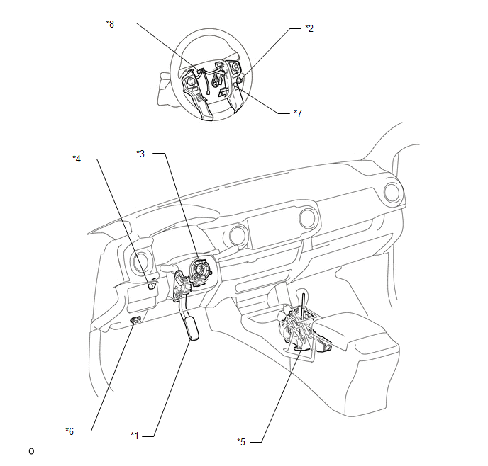
*1 |
ACCELERATOR PEDAL SENSOR ASSEMBLY |
*2 |
CRUISE CONTROL MAIN SWITCH |
|
*3 |
STEERING ANGLE SENSOR (SPIRAL CABLE WITH SENSOR SUB-ASSEMBLY) |
*4 |
STOP LIGHT SWITCH ASSEMBLY |
|
*5 |
TRANSMISSION CONTROL SWITCH (TRANSMISSION FLOOR SHIFT ASSEMBLY ) |
*6 |
DLC3 |
|
*7 |
DISTANCE CONTROL SWITCH (STEERING PAD SWITCH ASSEMBLY) |
*8 |
CRUISE CONTROL SWITCH WIRE |
ILLUSTRATION
|
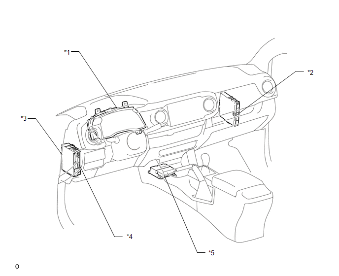
*1 |
COMBINATION METER ASSEMBLY |
*2 |
ECM |
|
*3 |
DRIVER SIDE JUNCTION BLOCK - IG1 NO. 2 FUSE - ECU-IG NO. 2 FUSE - IG1 NO. 1 FUSE - BKUP LP NO. 3 FUSE |
*4 |
MAIN BODY ECU (MULTIPLEX NETWORK BODY ECU) |
|
*5 |
YAW RATE AND ACCELERATION SENSOR (AIRBAG SENSOR ASSEMBLY) |
- |
- |

 Precaution
PRECAUTION
IGNITION SWITCH EXPRESSIONS
(a) The type of ignition switch used on this model differs according to the specifications
of the vehicle. The expressions listed in the table below are used ...
Other materials:
Inspection
INSPECTION
PROCEDURE
1. INSPECT MAGNET CLUTCH ASSEMBLY
(a) Inspect the magnet clutch assembly.
Text in Illustration
*a
Component without harness connected
(Magnet Clutch Assembly)
...
Dtc Check / Clear
DTC CHECK / CLEAR
1. CHECK DTC (CHECK USING TECHSTREAM)
(a) Connect the Techstream to the DLC3.
(b) Turn the ignition switch to ON.
(c) Turn the Techstream on.
(d) Enter the following menus: Body Electrical / Navigation System / Trouble
Codes.
(e) Check for DTCs, and then write them down.
( ...
Vehicle Speed Sensor (C1A45)
DESCRIPTION
The blind spot monitor sensor receives vehicle speed signals from the skid control
ECU (brake actuator assembly) via CAN communication.
DTC Code
DTC Detection Condition
Trouble Area
C1A45
A fail flag is transmitted from the ...
