Toyota Tacoma (2015-2018) Service Manual: Disassembly
DISASSEMBLY
PROCEDURE
1. REMOVE MILLIMETER WAVE RADAR WIRE (w/ Toyota Safety Sense P)
Click here .gif)
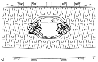
2. REMOVE MILLIMETER WAVE RADAR SENSOR ASSEMBLY (w/ Toyota Safety Sense P)
Click here
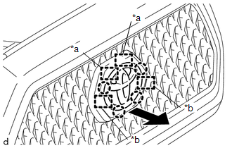
3. REMOVE NO. 1 RADIATOR GRILLE GARNISH
(a) When Replacing the No. 1 Radiator Grille Garnish:
(1) Apply protective tape around the spring nut.
.png) |
Protective Tape |
|
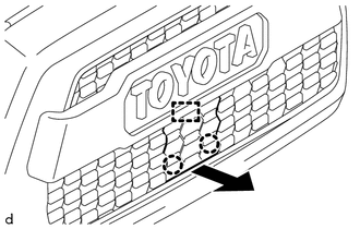
(2) Using a plier nipper (side cutters), cut the No. 1 radiator grille garnish at the positions shown in the illustration. |
|
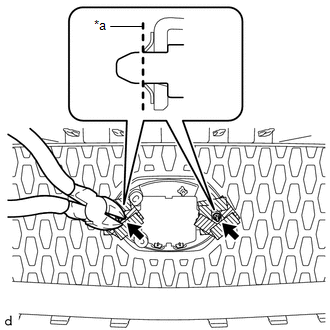
|
(3) Push the No. 1 radiator grille garnish to remove the 2 spring nuts as shown in the illustration. CAUTION: Make sure to cover the spring nuts with a piece of cloth or equivalent to prevent them from flying off during removal. |
|
|
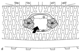
(4) For type A and type B, disengage the 4 claws and 2 pins as shown in the illustration to remove the No. 1 radiator grille garnish. |
|
|
(5) For type C, disengage the 2 claws and the guide as shown in the illustration to remove the No. 1 radiator grille garnish. |
|
(b) When Replacing the Radiator Grille Sub-Assembly:
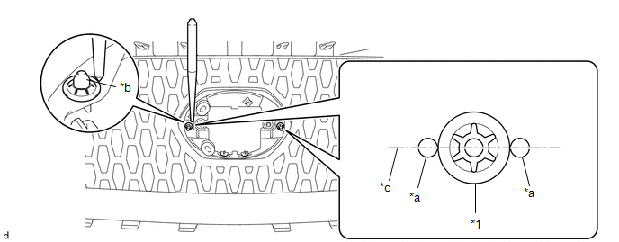
(1) Using a center punch, make a depression at the positions shown in the illustration.
|
*1 |
Spring Nut |
- |
- |
|
*a |
Depression |
*b |
Pin of No. 1 Radiator Grille Garnish |
|
*c |
Center Line |
- |
- |
HINT:
- Make sure to make the depressions so they are aligned with the center line of the pin of the No. 1 radiator grille garnish.
- Make sure to make the depressions correctly so that a plier nipper (side cutters) can be used to pinch the spring nuts.
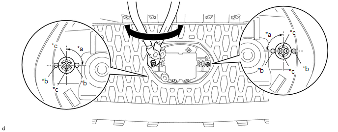
(2) Using a plier nipper (side cutters), rotate the 2 spring nuts to align the cutouts of each spring nut as shown in the illustration.
|
*a |
90° |
*b |
Depression |
|
*c |
Cutout |
- |
- |
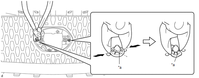
(3) Using a plier nipper (side cutters), deform each spring nut as shown in the illustration and then remove the 2 spring nuts.
|
*a |
Cutout |
- |
- |
|
(4) For type A and type B, disengage the 4 claws and 2 guides and 2 pins as shown in the illustration to remove the No. 1 radiator grille garnish. |
|
|
(5) For type C, disengage the 2 claws and 3 guides as shown in the illustration to remove the No. 1 radiator grille garnish. |
|

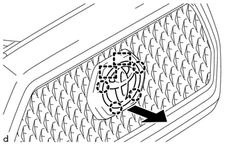
4. REMOVE RADIATOR GRILLE MOULDING
|
(a) Remove the 8 screws. |
|
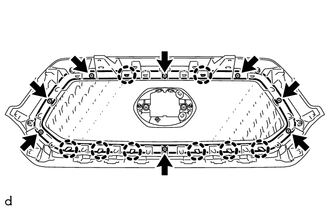
(b) Disengage the 8 claws to remove the radiator grille moulding.
 Removal
REMOVAL
PROCEDURE
1. REMOVE RADIATOR GRILLE
(a) w/ Toyota Safety Sense P
(1) Disconnect the connector.
(2) Disengage the clamp.
(b ...
 Installation
INSTALLATION
PROCEDURE
1. INSTALL RADIATOR GRILLE
(a) Engage the 10 guides to install the radiator grille.
(b) Install the 2 clips.
(c) Install the 2 screws.
(d) Remove the protective tape.
(e) ...
Other materials:
Disposal
DISPOSAL
CAUTION / NOTICE / HINT
CAUTION:
Before performing pre-disposal deployment of any SRS part, review and closely
follow all applicable environmental and hazardous material regulations. Pre-disposal
deployment may be considered hazardous material treatment.
PROCEDURE
1. PRECAUTION
...
Front Blower Resistor
Inspection
INSPECTION
PROCEDURE
1. INSPECT BLOWER RESISTOR
(a) Check the resistance.
(1) Measure the resistance according to the value(s) in the table below.
Standard Resistance:
Tester Connection
Condition
Specified
...
Removal
REMOVAL
PROCEDURE
1. REMOVE ROOF HEADLINING ASSEMBLY (for LED Type Stop Light)
for Double Cab:
(See page
)
for Access Cab:
(See page
)
2. REMOVE CENTER STOP LIGHT ASSEMBLY (for Bulb Type Stop Light)
(a) Apply protective tape around the center stop light as ...
