Toyota Tacoma (2015-2018) Service Manual: Clutch Switch Circuit
DESCRIPTION
Clutch switch circuit inspection is necessary for manual transmission vehicles.
When the clutch pedal is released, the ECM receives the positive (+) battery voltage through the ECU-IG NO. 2 fuse and ignition switch. While the clutch pedal is depressed, the clutch switch assembly sends a signal to terminal D of the ECM. The ECM cancels cruise control when terminal D receives the signal (voltage of below 1 V).
WIRING DIAGRAM
.png)
CAUTION / NOTICE / HINT
NOTICE:
Inspect the fuses for circuits related to this system before performing the following inspection procedure.
PROCEDURE
|
1. |
CHECK HARNESS AND CONNECTOR (ECM - BATTERY) |
|
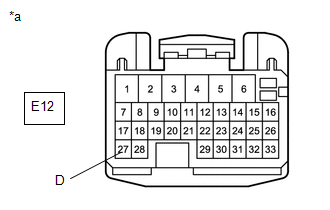
(a) Disconnect the ECM connector. |
|
(b) Turn the ignition switch to the ON position.
(c) Measure the voltage according to the value(s) in the table below.
Standard Voltage:
|
Tester Connection |
Condition |
Specified Condition |
|---|---|---|
|
E12-27 (D) - Body ground |
Clutch pedal depressed |
Below 1 V |
|
E12-27 (D) - Body ground |
Clutch pedal released |
11 to 14 V |
(d) Reconnect the ECM connector.
|
Proceed to |
|
OK |
|
NG |
| OK | .gif) |
PROCEED TO PROCEED TO NEXT SUSPECTED AREA SHOWN IN PROBLEM SYMPTOMS TABLE |
|
.gif)
|
2. |
INSPECT CLUTCH SWITCH ASSEMBLY |
|
(a) Remove the clutch switch assembly. Click here |
|
.gif)
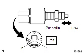
(b) Measure the resistance according to the value(s) in the table below.
Standard Resistance:
|
Tester Connection |
Condition |
Specified Condition |
|---|---|---|
|
C14-1 - C14-2 |
Switch pin free |
10 kΩ or higher |
|
C14-1 - C14-2 |
Switch pin pushed in |
Below 1 Ω |
(c) Reinstall the clutch switch.
|
Proceed to |
|
OK |
|
NG |
| NG | |
REPLACE CLUTCH SWITCH ASSEMBLY |
|
|
3. |
CHECK HARNESS AND CONNECTOR (CLUTCH SWITCH ASSEMBLY - ECM) |
(a) Disconnect the E12 ECM connector.
(b) Disconnect the C14 clutch switch assembly connector.
(c) Measure the resistance according to the value(s) in the table below.
Standard Resistance:
|
Tester Connection |
Condition |
Specified Condition |
|---|---|---|
|
C14-2 - Body ground |
Always |
10 kΩ or higher |
|
C14-2 - E12-27 (D) |
Always |
Below 1 Ω |
(d) Reconnect the clutch switch connector.
(e) Reconnect the ECM connector.
|
Proceed to |
|
OK |
|
NG |
| OK | |
REPAIR OR REPLACE HARNESS OR CONNECTOR (CLUTCH SWITCH ASSEMBLY - BATTERY) |
| NG | |
REPAIR OR REPLACE HARNESS OR CONNECTOR (CLUTCH SWITCH ASSEMBLY - ECM) |
 Vehicle Information Not Obtained (C1A02)
DESCRIPTION
When a new millimeter wave radar sensor assembly is installed, it receives vehicle
specification information (destination, steering wheel position, 2WD or 4WD, etc.)
from the main bod ...
 Cruise Control Switch Circuit
DESCRIPTION
The cruise control main switch is used to turn the dynamic radar cruise control
system on and off, as well as operate 7 functions: SET, - (COAST), TAP-DOWN, RES
(RESUME), + (ACCEL), T ...
Other materials:
Daytime Running Light Relay
Inspection
INSPECTION
PROCEDURE
1. INSPECT NO. 1 DAY TIME RUNNING LIGHT RELAY
(a) Check the resistance.
(1) Measure the resistance according to the value(s) in the table below.
Standard:
Tester Connection
Condition
Specified ...
Voice is not Recognized
PROCEDURE
1.
CHECK CONDITION
(a) Check if the system voice recognition level is low when recognizing a particular
voice.
Result
Result
Proceed to
System voice recognition level is low with any voice
A
...
Dtc Check / Clear
DTC CHECK / CLEAR
1. CHECK DTC (CHECK USING TECHSTREAM)
(a) Connect the Techstream to the DLC3.
(b) Turn the ignition switch to ON.
(c) Turn the Techstream on.
(d) Enter the following menus: Body Electrical / Navigation System / Trouble
Codes.
(e) Check for DTCs, and then write them down.
( ...
