Toyota Tacoma (2015-2018) Service Manual: Installation
INSTALLATION
PROCEDURE
1. INSTALL MAIN BODY ECU (MULTIPLEX NETWORK BODY ECU)
NOTICE:
- Make sure that the connecting surfaces are free of foreign matter.
- Do not touch the main body ECU (multiplex network body ECU) connector.
|
(a) Set the main body ECU (multiplex network body ECU) to the position where the 2 guides of the main body ECU (multiplex network body ECU) contacts the housing sidewall of the driver side junction block as shown in the illustration. Text in Illustration
HINT: Make sure to keep the angle at 20┬░ or more as shown in the illustration. |
|
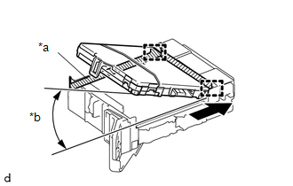
|
(b) While keeping the main body ECU (multiplex network body ECU) in contact with driver side junction block (axis of rotation), lower it as shown in the illustration. |
|
|
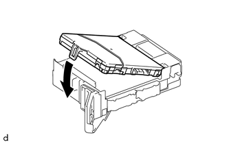
(c) Press the push area until the claw engages to install the main body ECU (multiplex network body ECU). Text in Illustration
NOTICE:
HINT: If a click sound cannot be heard, visually check the engagement of the lock. The engagement can also be confirmed if the main body ECU (multiplex network body ECU) and driver side junction block are flush. |
|
2. INSTALL DRIVER SIDE JUNCTION BLOCK
(a) Connect the 2 connectors on the back side.
(b) Install the driver side junction block with the 2 nuts.
(c) Connect the 5 connectors on the front side.
3. INSTALL INSTRUMENT PANEL LOWER FINISH PANEL SUB-ASSEMBLY
(See page .gif) )
)
 Components
COMPONENTS
ILLUSTRATION
ILLUSTRATION
...
 Removal
REMOVAL
PROCEDURE
1. REMOVE INSTRUMENT PANEL LOWER FINISH PANEL SUB-ASSEMBLY
(See page )
2. REMOVE DRIVER SIDE JUNCTION BLOCK
(a) Disconnect the 5 connectors on the front side.
...
Other materials:
Data List / Active Test
DATA LIST / ACTIVE TEST
1. READ DATA LIST
HINT:
Using the Techstream to read the Data List allows the values or states of switches,
sensors, actuators and other items to be read without removing any parts. This non-intrusive
inspection can be very useful because intermittent conditions or sig ...
Clutch Switch Circuit
DESCRIPTION
While depressing the clutch pedal, the clutch start switch assembly sends a signal
to terminal MTN of the 4 wheel drive control ECU. While the signal is input, switching
between H4 and L4 is possible.
WIRING DIAGRAM
PROCEDURE
1.
READ VALUE USING TECHSTREA ...
Removal
REMOVAL
CAUTION / NOTICE / HINT
CAUTION:
Some of these service operations affect the SRS airbag system. Read the precautionary
notices concerning the SRS airbag system before servicing (See page
).
HINT:
Use the same procedure for both the RH and LH sides.
The procedure describe ...
