Toyota Tacoma (2015-2018) Service Manual: System Diagram
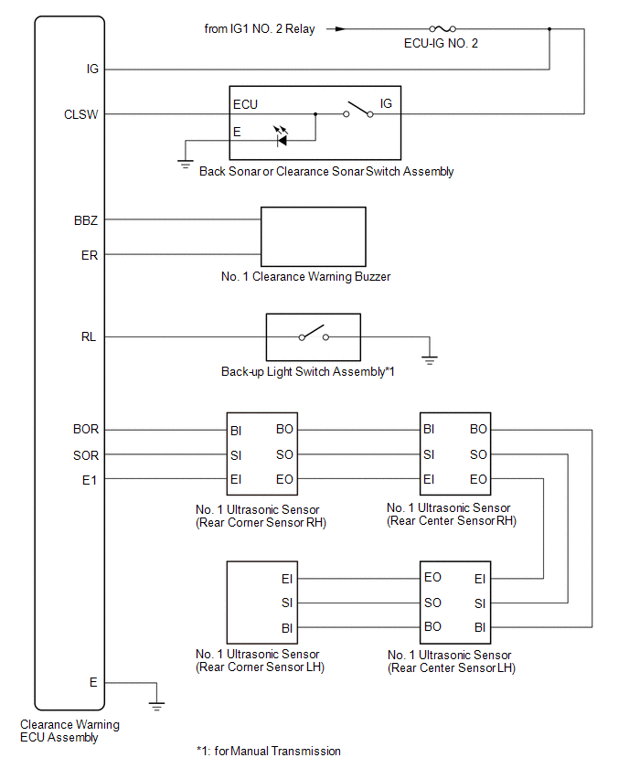
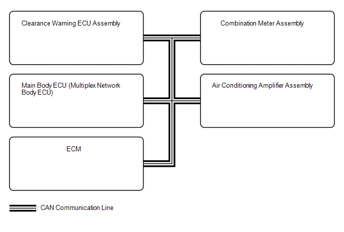
SYSTEM DIAGRAM
 Communication Table
|
Sender |
Receiver |
Signal |
Line |
|---|---|---|---|
|
Main Body ECU (Multiplex Network Body ECU) |
Clearance Warning ECU Assembly |
Destination information signal |
CAN Communication Line |
|
ECM |
Clearance Warning ECU Assembly |
Shift position signal |
CAN Communication Line |
|
Combination Meter Assembly |
Clearance Warning ECU Assembly |
Vehicle speed signal |
CAN Communication Line |
|
Air Conditioning Amplifier Assembly |
Clearance Warning ECU Assembly |
Ambient temperature display signal |
CAN Communication Line |
|
Clearance Warning ECU Assembly |
Combination Meter Assembly |
|
CAN Communication Line |
 Parts Location
PARTS LOCATION
ILLUSTRATION
ILLUSTRATION
...
 How To Proceed With Troubleshooting
CAUTION / NOTICE / HINT
HINT:
Use the following procedure to troubleshoot the intuitive parking assist
system.
*: Use the Techstream.
PROCEDURE
1.
VEHI ...
Other materials:
On-vehicle Inspection
ON-VEHICLE INSPECTION
PROCEDURE
1. INSPECT CURTAIN SHIELD AIRBAG ASSEMBLY (for Vehicle not Involved in Collision)
(a) Perform a Diagnostic System Check (See page
).
(b) With the curtain shield airbag installed on the vehicle, perform
a visual check. If any of the defects mention ...
Terminals Of Ecu
TERMINALS OF ECU
Text in Illustration
*a
Component without harness connected
(Skid Control ECU [Brake Actuator Assembly])
-
-
Terminal No. (Symbol)
Terminal Description
1 (GND2)
Pump motor g ...
System Description
SYSTEM DESCRIPTION
PRE-COLLISION SYSTEM DESCRIPTION
(a) The pre-collision system uses the pre-collision warning control, pre-collision
brake assist control and pre-collision braking control to help avoid a collision
or reduce the impact if it determines that the possibility of a collision is h ...
