Toyota Tacoma (2015-2018) Service Manual: Installation
INSTALLATION
PROCEDURE
1. INSPECT FRONT PROPELLER SHAFT ASSEMBLY (with Grease Fitting)
HINT:
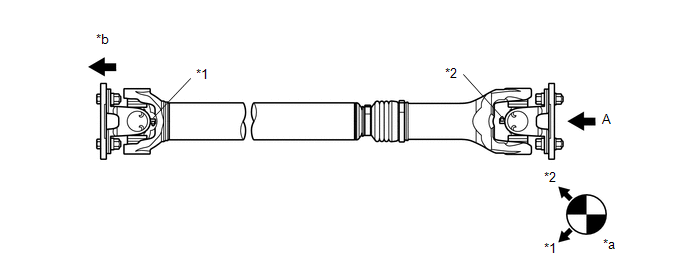
When replacing the spider bearing, make sure that the grease fitting assembly hole is facing in the direction shown in the illustration.
 Text in Illustration
|
*1 |
No. 1 Grease Fitting |
*2 |
No. 2 Grease Fitting |
|
*a |
View A |
*b |
Front Side |
2. INSTALL FRONT PROPELLER SHAFT ASSEMBLY
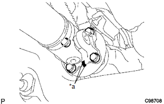
(a) Align the matchmarks on the propeller shaft flange and differential flange.
Text in Illustration|
*a |
Matchmark |
(b) Install the propeller shaft with the 4 bolts, 4 nuts and 4 washers.
Torque:
88 N·m {899 kgf·cm, 65 ft·lbf}
|
(c) Align the matchmarks on the propeller shaft flange and transfer flange. Text in Illustration
|
|
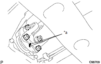
(d) Install the propeller shaft with the 4 nuts and 4 washers.
Torque:
88 N·m {899 kgf·cm, 65 ft·lbf}
3. INSTALL PROPELLER SHAFT HEAT INSULATOR BRACKET SUB-ASSEMBLY
.png)
(a) Install the propeller shaft heat insulator bracket with the 2 bolts.
Torque:
16 N·m {160 kgf·cm, 12 ft·lbf}
4. INSTALL FRONT NO. 2 EXHAUST PIPE ASSEMBLY (for 2GR-FKS)
.gif)
 Reassembly
REASSEMBLY
PROCEDURE
1. INSTALL FRONT PROPELLER SHAFT UNIVERSAL JOINT SPIDER BEARING
(a) Apply MP grease to a new spider and spider bearing.
(b) Fit the spider into the flange yoke.
...

Other materials:
How To Proceed With Troubleshooting
CAUTION / NOTICE / HINT
HINT:
Use this procedure to troubleshoot the seat heater system.
*: Use the Techstream.
PROCEDURE
1.
VEHICLE BROUGHT TO WORKSHOP
NEXT
2.
...
Utility
UTILITY
NOTICE:
If the forward recognition camera has been replaced due to a malfunction in the
lane departure alert system, be sure to perform Recognition Camera/Target Position
Memory and Optical Axis Learning. Otherwise all systems that use the forward recognition
camera may be affected.
...
Installation
INSTALLATION
PROCEDURE
1. INSTALL TRANSMISSION WIRE
(a) Coat 2 new O-rings with ATF, and install them to the 2 temperature sensors.
(b) Coat a new O-ring with ATF, and install it to the transmission wire.
(c) Install the transmission wire to the automatic transmission case sub-assembly
with t ...
