Toyota Tacoma (2015-2018) Service Manual: Reassembly
REASSEMBLY
PROCEDURE
1. INSTALL FRONT PROPELLER SHAFT UNIVERSAL JOINT SPIDER BEARING
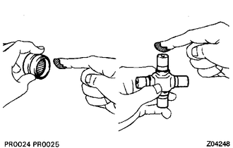
(a) Apply MP grease to a new spider and spider bearing.
(b) Fit the spider into the flange yoke.
|
(c) Measure dimension A between the snap ring grooves. |
|
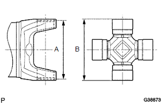
(d) Insert the spider bearing into the spider journal portion, and then measure dimension B of the universal joint.
NOTICE:
When measuring dimension B, fix the spider and needle roller bearings in a vise and hold them firmly together.
|
(e) Select snap rings to make dimensions A and B the same. Snap Ring Type:
NOTICE:
|
|
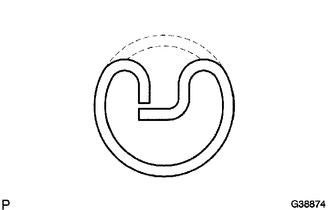
|
(f) Insert the spider into the yoke, and then using SST, press in the spider bearing into the snap ring groove. SST: 09332-25010 |
|
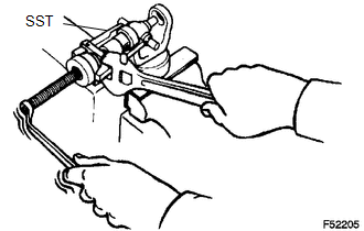
(g) Press in the spider bearing on the opposite side in the same way.
NOTICE:
When pressing in the spider bearing, be careful not to damage its lip.
|
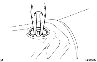
(h) Using needle-nose pliers, install new snap rings into the grooves of the yoke. |
|
2. INSPECT FRONT PROPELLER SHAFT UNIVERSAL JOINT SPIDER BEARING
(a) Check the spider bearings for wear and damage.
(b) Check each spider bearing's axial play by turning the yoke while holding the shaft tightly.
Maximum bearing axial play:
0 to 0.05 mm (0 to 0.002 in.)
 Inspection
INSPECTION
PROCEDURE
1. INSPECT FRONT PROPELLER SHAFT ASSEMBLY
(a) Using a dial indicator, check the propeller shaft runout.
Maximum runout:
0.6 mm (0.024 in.)
If the shaft runout is greater ...
 Installation
INSTALLATION
PROCEDURE
1. INSPECT FRONT PROPELLER SHAFT ASSEMBLY (with Grease Fitting)
HINT:
When replacing the spider bearing, make sure that the grease fitting assembly
hole is facing in the d ...
Other materials:
Removal
REMOVAL
PROCEDURE
1. REMOVE REAR SEAT CUSHION ASSEMBLY
2. REMOVE NO. 4 ROOM PARTITION COVER LH
3. REMOVE NO. 4 ROOM PARTITION COVER RH
4. REMOVE NO. 3 ROOM PARTITION COVER
5. REMOVE BACK PANEL GARNISH HOLE PLUG
6. REMOVE BACK PANEL TRIM
7. REMOVE FRONT DOOR SCUFF PLATE ...
Light Sensor Circuit Malfunction (B1244)
DESCRIPTION
This DTC is output when a failure of the automatic light control sensor circuit
is detected.
DTC Code
DTC Detection Condition
Trouble Area
B1244
When either condition below is met:
Malfunction of light sensor ...
Diagnostic Trouble Code Chart
DIAGNOSTIC TROUBLE CODE CHART
If a DTC is displayed during the DTC check, check the parts listed in
the table below and proceed to the "See page" given.
*1: "Comes on" means the Malfunction Indicator Lamp (MIL) illuminates.
*2: "DTC stored" means ...
