Toyota Tacoma (2015-2018) Service Manual: Components
COMPONENTS
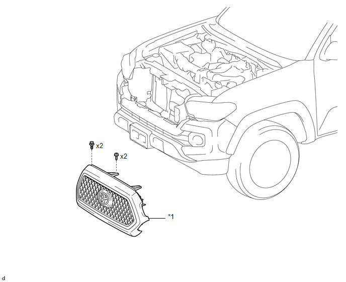
ILLUSTRATION
|
*1 |
RADIATOR GRILLE |
- |
- |
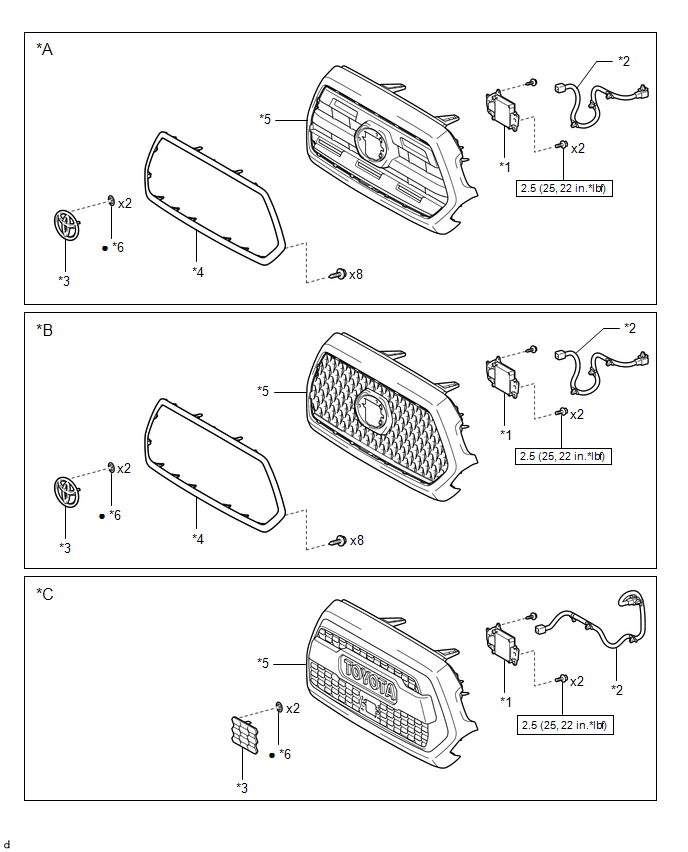
ILLUSTRATION
|
*A |
for Type A |
*B |
for Type B |
|
*C |
for Type C |
- |
- |
|
*1 |
MILLIMETER WAVE RADAR SENSOR ASSEMBLY |
*2 |
MILLIMETER WAVE RADAR WIRE |
|
*3 |
NO. 1 RADIATOR GRILLE GARNISH |
*4 |
RADIATOR GRILLE MOULDING |
|
*5 |
RADIATOR GRILLE SUB-ASSEMBLY |
*6 |
SPRING NUT |
.png) |
N*m (kgf*cm, ft.*lbf): Specified torque |
â—Ź |
Non-reusable part |
 Radiator Grille
...
 Removal
REMOVAL
PROCEDURE
1. REMOVE RADIATOR GRILLE
(a) w/ Toyota Safety Sense P
(1) Disconnect the connector.
(2) Disengage the clamp.
(b ...
Other materials:
Vehicle Lift And Support Locations
VEHICLE LIFT AND SUPPORT LOCATIONS
1. NOTICE ABOUT VEHICLE CONDITION WHEN JACKING UP VEHICLE
(a) The vehicle must be unloaded before jacking up / lifting up the vehicle.
Never jack up / lift up a heavily loaded vehicle.
(b) When removing heavy parts such as the engine and transmission, the cent ...
System Description
SYSTEM DESCRIPTION
GENERAL
The cruise control main switch is used to turn the dynamic radar cruise control
system on and off, as well as operate 7 functions: SET, - (COAST), TAP-DOWN, RES
(RESUME), + (ACCEL), TAP-UP and CANCEL. The SET, TAP-DOWN, and - (COAST) functions,
and the RES (RESUME) ...
Terminals Of Ecu
TERMINALS OF ECU
1. AIRBAG SENSOR ASSEMBLY
Terminal No.
Terminal Symbol
Destination
A21-1
P2+
Instrument panel passenger without door airbag assembly (Front passenger
side squib 2nd step)
A21-2
...
