Toyota Tacoma (2015-2018) Service Manual: Inspection
INSPECTION
PROCEDURE
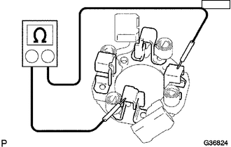
1. INSPECT MAGNET STARTER SWITCH ASSEMBLY
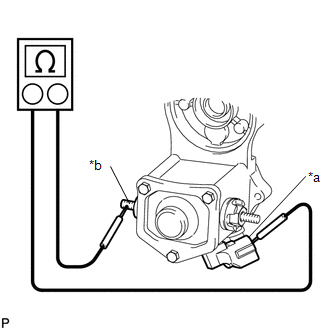
(a) Inspect the pull-in coil.
|
(1) Measure the resistance according to the value(s) in the table below. Text in Illustration
Standard Resistance:
If the result is not as specified, replace the magnet starter switch assembly. |
|
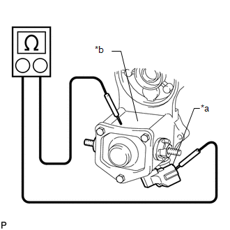
(b) Inspect the holding coil.
|
(1) Measure the resistance according to the value(s) in the table below. Text in Illustration
Standard Resistance:
If the result is not as specified, replace the magnet starter switch assembly. |
|
2. INSPECT BRUSH
|
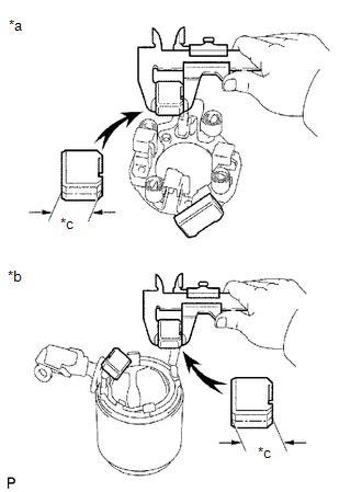
(a) Using a vernier caliper, measure the brush length. Text in Illustration
Standard length: 15.5 mm (0.610 in.) Minimum length: 8.5 mm (0.335 in.) If the length is less than the minimum, replace the starter brush holder assembly and starter yoke assembly. |
|
3. INSPECT STARTER BRUSH HOLDER ASSEMBLY
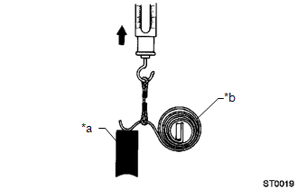
(a) Check the brush spring load.
|
(1) Take a pull scale reading immediately after the brush spring separates from the brush. Text in Illustration
Standard spring load: 17.6 to 23.5 N (1.8 to 2.4 kgf, 4.0 to 5.3 lbf) Minimum spring load: 11.8 N (1 kgf, 2.7 lbf) If the spring load is less than the minimum, replace the starter brush holder assembly. |
|
(b) Inspect the insulation.
|
(1) Measure the resistance according to the value(s) in the table below. Standard Resistance:
If the result is not as specified, replace the starter brush holder assembly. |
|
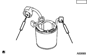
4. INSPECT STARTER YOKE ASSEMBLY
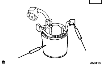
(a) Inspect the field coil for an open circuit.
|
(1) Measure the resistance according to the value(s) in the table below. Standard Resistance:
If the result is not as specified, replace the starter yoke assembly. |
|
|
(2) Measure the resistance according to the value(s) in the table below. Standard Resistance:
If the result is not as specified, replace the starter yoke assembly. |
|
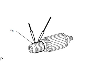
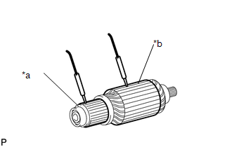
5. INSPECT STARTER ARMATURE ASSEMBLY
(a) Check the commutator for dirt and/or burns on the surface.
If the surface is dirty or burnt, correct it with sandpaper (No. 400) or a lathe. If necessary, replace the starter armature assembly.
(b) Inspect the commutator for an open circuit.
|
(1) Measure the resistance according to the value(s) in the table below. Text in Illustration
Standard Resistance:
If the result is not as specified, replace the starter armature assembly. |
|
(c) Inspect the commutator for a short circuit.
|
(1) Measure the resistance according to the value(s) in the table below. Text in Illustration
Standard Resistance:
If the result is not as specified, replace the starter armature assembly. |
|
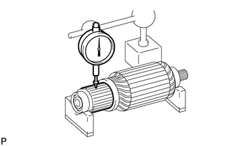
(d) Check the commutator circle runout.
(1) Place the bearing of armature on V-blocks.
|
(2) Using a dial indicator, measure the circle runout. Maximum runout: 0.05 mm (0.00197 in.) If the circle runout is more than the maximum, replace the starter armature assembly. |
|
|
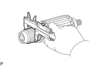
(e) Using a vernier caliper, measure the commutator diameter. Standard diameter: 30.0 mm (1.18 in.) Minimum diameter: 29.0 mm (1.14 in.) If the diameter is less than the minimum, replace the starter armature assembly. |
|
|
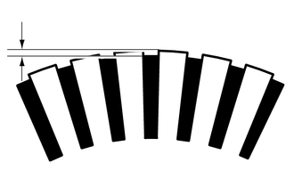
(f) Using a vernier caliper, measure the undercut depth of the commutator. Standard undercut depth: 0.6 mm (0.0236 in.) Minimum undercut depth: 0.2 mm (0.00787 in.) If the undercut depth is less than the minimum, replace the starter armature assembly. |
|
6. INSPECT STARTER CLUTCH SUB-ASSEMBLY
(a) Rotate the pinion gear clockwise and check that it turns freely. Try to rotate the pinion gear counterclockwise and check that it locks.
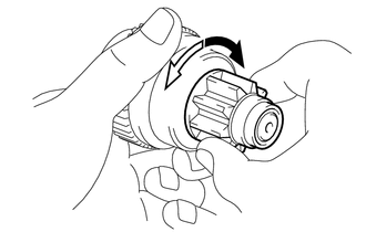 Text in Illustration
.png) |
Free |
.png) |
Lock |
If the result is not as specified, replace the starter clutch sub-assembly.
(b) Turn the pinion gear by hand while applying inward force and check the movement of the bearing.
If resistance is felt or the bearing sticks, replace the starter clutch sub-assembly.
 Disassembly
DISASSEMBLY
PROCEDURE
1. REMOVE STARTER YOKE ASSEMBLY
(a) Remove the nut and disconnect the lead wire from terminal C.
(b) Remove the 2 bolts.
...
 Removal
REMOVAL
PROCEDURE
1. PRECAUTION
NOTICE:
After turning the engine switch off, waiting time may be required before disconnecting
the cable from the battery terminal. Therefore, make sure to read t ...
Other materials:
Reassembly
REASSEMBLY
CAUTION / NOTICE / HINT
NOTICE:
When installing the hood bulge protector, heat the hood bulge surface
using the infrared light.
Do not heat the hood bulge excessively.
Item
Temperature
Hood Bulge
...
Removal
REMOVAL
CAUTION / NOTICE / HINT
NOTICE:
When replacing the windshield glass of a vehicle equipped with a forward recognition
camera, make sure to use a Toyota genuine part. If a non-Toyota genuine part is
used, the forward recognition camera may not be able to be installed due to a missing
...
Yaw Rate Sensor Malfunction (C1436)
DESCRIPTION
The skid control ECU (brake actuator assembly) receives signals from the yaw
rate and acceleration sensor (airbag sensor assembly) via the CAN communication
system.
The airbag sensor assembly has a built-in yaw rate sensor and detects the vehicle
condition.
If there is trouble i ...
