Toyota Tacoma (2015-2018) Service Manual: Removal
REMOVAL
CAUTION / NOTICE / HINT
NOTICE:
When replacing the windshield glass of a vehicle equipped with a forward recognition camera, make sure to use a Toyota genuine part. If a non-Toyota genuine part is used, the forward recognition camera may not be able to be installed due to a missing bracket. Also, the dynamic radar cruise control system, lane departure alert system, pre-crash safety system, forward recognition camera system or automatic high beam system may not operate properly due to a difference in the transmissivity or black ceramic border.
PROCEDURE
1. PRECAUTION
NOTICE:
After turning the ignition switch off, waiting time may be required before disconnecting the cable from the battery terminal. Therefore, make sure to read the disconnecting the cable from the battery terminal notice before proceeding with work.
Click here .gif)
2. DISCONNECT CABLE FROM NEGATIVE BATTERY TERMINAL
NOTICE:
When disconnecting the cable, some systems need to be initialized after the cable is reconnected.
Click here
3. REMOVE FRONT WIPER ARM HEAD CAP
Click here
4. REMOVE WINDSHIELD WIPER ARM AND BLADE ASSEMBLY LH
Click here
5. REMOVE WINDSHIELD WIPER ARM AND BLADE ASSEMBLY RH
HINT:
Use the same procedure as for the LH side.
6. REMOVE FRONT FENDER UPPER PROTECTOR LH
Click here
7. REMOVE FRONT FENDER UPPER PROTECTOR RH
HINT:
Use the same procedure as for the LH side.
8. REMOVE COWL TOP VENTILATOR LOUVER SUB-ASSEMBLY
Click here
9. REMOVE INNER REAR VIEW MIRROR COVER (w/ EC Mirror)
Click here
10. REMOVE INNER REAR VIEW MIRROR ASSEMBLY (w/ EC Mirror)
Click here
11. REMOVE INNER REAR VIEW MIRROR ASSEMBLY (w/o EC Mirror)
Click here
12. REMOVE FORWARD RECOGNITION CAMERA (w/ Toyota Safety Sense)
Click here
13. REMOVE FORWARD RECOGNITION WITH HEATER HOOD SUB-ASSEMBLY (w/ Toyota Safety Sense)
Click here
14. DISCONNECT FRONT DOOR OPENING TRIM WEATHERSTRIP LH
(a) Disconnect the front door opening trim weatherstrip LH to the extent which allows the removal of the front pillar garnish.
15. DISCONNECT FRONT DOOR OPENING TRIM WEATHERSTRIP RH
HINT:
Use the same procedure as for the LH side.
16. REMOVE ASSIST GRIP SUB-ASSEMBLY
Click here
17. REMOVE FRONT PILLAR GARNISH LH
Click here
18. REMOVE FRONT PILLAR GARNISH RH
HINT:
Use the same procedure as for the LH side.
19. REMOVE ROOF CONSOLE BOX ASSEMBLY
Click here
20. REMOVE VISOR ASSEMBLY LH (w/ Vanity Light)
Click here
21. REMOVE VISOR ASSEMBLY RH (w/ Vanity Light)
HINT:
Use the same procedure as for the LH side.
22. REMOVE VISOR ASSEMBLY LH (w/o Vanity Light)
Click here
23. REMOVE VISOR ASSEMBLY RH (w/o Vanity Light)
HINT:
Use the same procedure as for the LH side.
24. REMOVE VISOR HOLDER LH
Click here
25. REMOVE VISOR HOLDER RH
HINT:
Use the same procedure as for the LH side.
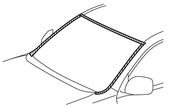
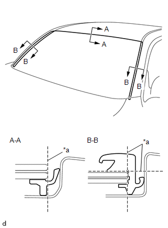
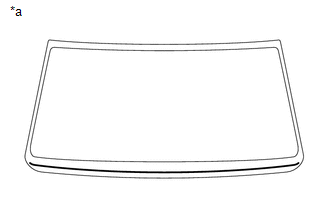
26. REMOVE WINDSHIELD GLASS
NOTICE:
The windshield glass may fall while performing this procedure. Therefore, use suction cups to hold the windshield glass from the outside of the vehicle.
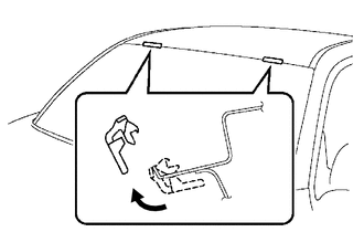
(a) Partially separate the roof headlining assembly enough to enable the windshield glass to be removed.
NOTICE:
Make sure not to cause any wrinkles or creases in the roof headlining assembly when separating it.
(b) Apply protective tape to the area around the installation position of the windshield glass on the vehicle body to prevent it from being scratched.
 Text in Illustration
.png) |
Protective Tape |
|
(c) Using a knife, cut off the windshield outside moulding as shown in the illustration. Text in Illustration
NOTICE:
|
|
(d) When reusing the windshield glass:
|
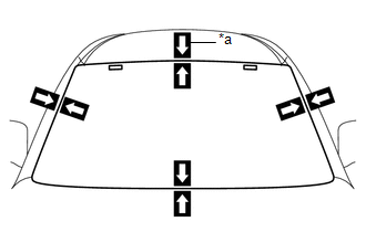
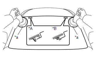
(1) Place matchmarks on the windshield glass sub-assembly and vehicle body at the locations indicated in the illustration. Text in Illustration
|
|
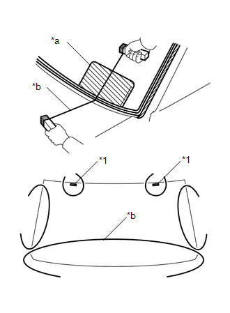
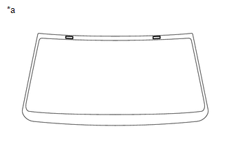
(e) Install the suction cups to the windshield glass.
(f) Pass a piano wire between the vehicle body and windshield glass sub-assembly from the interior.
 Text in Illustration
|
*1 |
Windshield Glass Stopper |
|
*a |
Plastic Sheet |
|
*b |
Piano Wire |
|
|
Protective Tape |
(g) Tie both wire ends to wooden blocks or similar objects that can serve as handles.
NOTICE:
- Do not forcefully brush the piano wire against the windshield glass.
- To prevent the safety pad from being scratched when removing the windshield glass, place a plastic sheet between the piano wire and safety pad.
(h) Cut off the adhesive by pulling the piano wire around the windshield glass sub-assembly.
NOTICE:
Be careful as the piano wire will break if it crosses itself.
|
(i) Using suction cups, disengage the 2 windshield glass stoppers to remove the windshield glass. Text in Illustration
|
|
27. REMOVE WINDSHIELD GLASS ADHESIVE DAM
(a) When reusing the windshield glass:
|
(1) Using a scraper, remove the windshield glass adhesive dam. Text in Illustration
NOTICE:
|
|
28. REMOVE NO. 1 WINDSHIELD GLASS STOPPER (for 1-piece Type)
(a) When reusing the windshield glass:
|
(1) Using a scraper, remove the 2 No. 1 windshield glass stoppers from the back side of the windshield glass. Text in Illustration
NOTICE:
|
|
29. REMOVE NO. 2 WINDSHIELD GLASS STOPPER (for 2-piece Type)
(a) When reusing the windshield glass:
|
(1) Using a scraper, remove the 2 No. 2 windshield glass stoppers from the back side of the windshield glass. Text in Illustration
NOTICE:
|
|
30. REMOVE NO. 1 WINDSHIELD GLASS STOPPER (for 2-piece Type)
|
(a) Remove the 2 No. 1 windshield glass stoppers from the vehicle body. NOTICE: Be sure to replace the No. 1 windshield glass stoppers with new ones. |
|
 Components
COMPONENTS
ILLUSTRATION
*1
COWL TOP VENTILATOR LOUVER SUB-ASSEMBLY
*2
FRONT FENDER UPPER PROTECTOR LH
*3
FRONT FENDER UPPER ...
 Installation
INSTALLATION
CAUTION / NOTICE / HINT
NOTICE:
When replacing the windshield glass of a vehicle equipped with a forward recognition
camera, make sure to use a Toyota genuine part. If a non-Toyota g ...
Other materials:
Inspection
INSPECTION
PROCEDURE
1. INSPECT CYLINDER BLOCK FOR WARPAGE
(a) Using a precision straightedge and feeler gauge, measure the warpage
of the contact surface of the cylinder head gasket.
Standard warpage:
0 to 0.05 mm (0 to 0.00197 in.)
Maximum warpage:
0.07 mm (0.00276 ...
Front Occupant Classification Sensor LH Circuit Malfunction (B1780)
DESCRIPTION
The occupant classification sensor front LH circuit consists of the occupant
detection ECU and the occupant classification sensor front LH.
DTC B1780 is set when a malfunction is detected in the occupant classification
sensor front LH circuit.
DTC No.
DTC Det ...
Installation
INSTALLATION
PROCEDURE
1. INSTALL REAR ENGINE OIL SEAL
(a) Apply MP grease to the lip of a new rear engine oil seal.
NOTICE:
Keep the lip free of foreign matter.
(b) Using SST, tap in a new rear engine oil seal until its surface is
flush with the rear engine oil seal retainer ed ...
