Toyota Tacoma (2015-2018) Service Manual: Disassembly
DISASSEMBLY
PROCEDURE
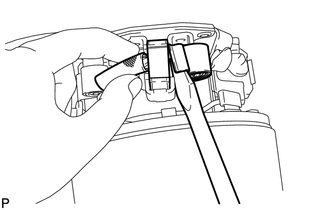
1. REMOVE STARTER YOKE ASSEMBLY
|
(a) Remove the nut and disconnect the lead wire from terminal C. |
|
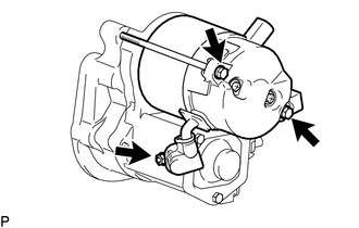
(b) Remove the 2 bolts.
(c) Pull out the starter yoke assembly and commutator end frame together with the starter armature assembly.
(d) Remove the O-ring from the starter yoke.
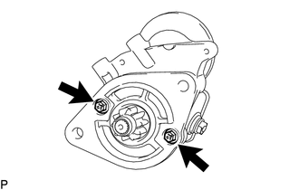
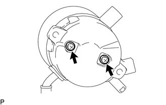
2. REMOVE MAGNET STARTER SWITCH ASSEMBLY
|
(a) Remove the 2 bolts and magnet starter switch assembly. |
|
|
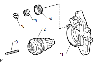
(b) Remove the idle gear, retainer, clutch roller, return spring and starter clutch sub-assembly from the starter drive housing assembly. Text in Illustration
|
|
|
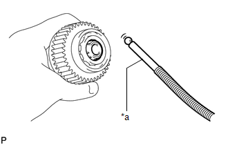
(c) Using a magnet hand, remove the steel ball from the starter clutch hole. Text in Illustration
|
|
3. REMOVE STARTER BRUSH HOLDER ASSEMBLY
|
(a) Remove the 2 screws and commutator end frame from the starter yoke assembly. NOTICE: While holding down the lead wire, remove the commutator end frame. |
|
(b) Remove the O-ring from the starter yoke assembly.
|
(c) Disconnect the 4 brushes from the starter brush holder assembly. (1) Using a screwdriver, hold back the brush spring. (2) Disconnect the brush from the starter brush holder assembly. |
|
(d) Remove the starter brush holder assembly.
4. REMOVE STARTER ARMATURE ASSEMBLY
(a) Remove the starter armature assembly from the starter yoke assembly.
 Components
COMPONENTS
ILLUSTRATION
ILLUSTRATION
...
 Inspection
INSPECTION
PROCEDURE
1. INSPECT MAGNET STARTER SWITCH ASSEMBLY
(a) Inspect the pull-in coil.
(1) Measure the resistance according to the value(s) in the table below.
Text in Illustra ...
Other materials:
System Description
SYSTEM DESCRIPTION
1. FUNCTION DESCRIPTION
(a) ABS (Anti-lock Brake System)
(1) The ABS helps prevent the wheels from locking when the brakes are applied
firmly or when braking on a slippery surface.
(b) EBD (Electronic Brake force Distribution)
(1) The EBD control utilizes ABS, and performs ...
On-vehicle Inspection
ON-VEHICLE INSPECTION
PROCEDURE
1. INSPECT DRIVER SEAT BELT WARNING LIGHT
HINT:
The seat belt warning light on the combination meter assembly is used for both
the driver seat and front passenger seat.
(a) Turn the ignition switch to ON.
(b) When the driver seat belt is not fastened, check th ...
Installation
INSTALLATION
PROCEDURE
1. INSTALL REAR SEATBACK HINGE SUB-ASSEMBLY
(a) Install the rear seatback hinge sub-assembly with the 2 bolts.
Torque:
30 N·m {306 kgf·cm, 22 ft·lbf}
2. INSTALL REAR SEATBACK ASSEMBLY
(a) Install the rear seatback assembly with the 2 bolts.
Torque:
37 N·m {377 k ...
