Toyota Tacoma (2015-2018) Service Manual: Removal
REMOVAL
PROCEDURE
1. PRECAUTION
NOTICE:
After turning the engine switch off, waiting time may be required before disconnecting the cable from the battery terminal. Therefore, make sure to read the disconnecting the cable from the battery terminal notice before proceeding with work.
Click here .gif)
2. DISCONNECT CABLE FROM NEGATIVE BATTERY TERMINAL
NOTICE:
When disconnecting the cable, some systems need to be initialized after the cable is reconnected.
Click here
3. REMOVE EXHAUST MANIFOLD SUB-ASSEMBLY LH
Click here
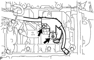
4. REMOVE STARTER COVER
|
(a) Remove the 3 bolts and starter cover. |
|
5. REMOVE STARTER ASSEMBLY
|
(a) Remove the bolt and disconnect the engine wire. |
|
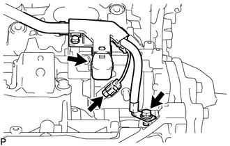
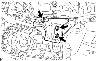
(b) Disconnect the starter assembly connector.
(c) Open the terminal cap.
|
(d) Remove the bolt, nut and disconnect the engine wire. |
|
|
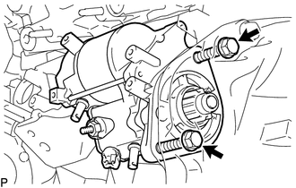
(e) Remove the 2 bolts and starter assembly. |
|
6. REMOVE FLYWHEEL HOUSING SIDE COVER
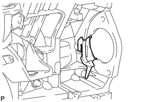
(a) Remove the flywheel housing side cover from the cylinder block sub-assembly.
 Inspection
INSPECTION
PROCEDURE
1. INSPECT MAGNET STARTER SWITCH ASSEMBLY
(a) Inspect the pull-in coil.
(1) Measure the resistance according to the value(s) in the table below.
Text in Illustra ...
 Installation
INSTALLATION
PROCEDURE
1. INSTALL FLYWHEEL HOUSING SIDE COVER
(a) Install the flywheel housing side cover to the cylinder block sub-assembly.
2. INSTALL STARTER ASSEMBLY
(a) Install the starter a ...
Other materials:
Removal
REMOVAL
PROCEDURE
1. PRECAUTION
NOTICE:
After turning the ignition switch off, waiting time may be required before disconnecting
the cable from the negative (-) battery terminal.
Therefore, make sure to read the disconnecting the cable from the negative (-)
battery terminal notices before p ...
Check Bus 2 Lines for Short Circuit
DESCRIPTION
There may be a short circuit between the CAN main bus lines and/or CAN branch
lines when the resistance between terminals 18 (CA4H) and 17 (CA4L) of the central
gateway ECU (network gateway ECU) is below 54 Ω.
Detection Item
Trouble Area
Resi ...
Rear Airbag Sensor LH Circuit Malfunction (B1635/24)
DESCRIPTION
The airbag sensor LH consists of parts such as the safing sensor, the diagnostic
circuit and the lateral deceleration sensor.
When the airbag sensor assembly receives signals from the lateral deceleration
sensor, it determines whether or not the SRS should be activated.
DTC B1635/ ...
