Toyota Tacoma (2015-2018) Service Manual: Inspection
INSPECTION
PROCEDURE
1. INSPECT BRAKE BOOSTER PUMP ASSEMBLY
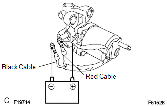
(a) Connect the positive (+) lead from the battery to the red cable of the pump, and the negative (-) lead to the black cable.
(b) Check the brake booster pump operation.
OK:
Operation sound is heard.
 Removal
REMOVAL
CAUTION / NOTICE / HINT
NOTICE:
Before starting the work, make sure that the ignition switch is off
and depress the brake pedal more than 20 times.
As high pressure is appli ...
 Reassembly
REASSEMBLY
PROCEDURE
1. INSTALL BRAKE BOOSTER ACCUMULATOR ASSEMBLY
(a) Place the brake booster pump in a vise with a cloth.
(b) Install the brake booster accumulator pipe, compression spring and ...
Other materials:
Front Stabilizer Bar
Components
COMPONENTS
ILLUSTRATION
Inspection
INSPECTION
PROCEDURE
1. INSPECT FRONT STABILIZER LINK ASSEMBLY
(a) Flip the ball joint stud back and forth 5 times, as shown in the illustration,
before installing the nut.
(b) Using a torque wrench, turn the nut continuously at a rate ...
Torque Converter Clutch Pressure Control Solenoid Control Circuit Electrical
(Shift Solenoid Valve SLU) (P2759)
DESCRIPTION
Refer to the system description for DTC P2757 (See page
).
DTC No.
DTC Detection Condition
Trouble Area
P2759
Open or short is detected in shift solenoid valve SLU circuit for 1 second
or more while driving (1 trip dete ...
How To Proceed With Troubleshooting
CAUTION / NOTICE / HINT
HINT:
The vehicle stability control system troubleshooting procedures are
based on the premise that the CAN communication system is functioning normally.
Check the CAN communication system first before troubleshooting the vehicle
stability control system ...
