Toyota Tacoma (2015-2018) Service Manual: Push Switch / Key Unlock Warning Switch Malfunction (B2780)
DESCRIPTION
This DTC is stored if the transponder key ECU assembly does not detect that the unlock warning switch assembly is ON even when the key is in the ignition key cylinder. Under normal conditions, the unlock warning switch assembly is ON when the key is in the ignition key cylinder.
|
DTC No. |
DTC Detection Condition |
Trouble Area |
DTC Output Confirmation Operation |
|---|---|---|---|
|
B2780 |
The unlock warning switch assembly is not detected as being on when the ignition switch is ON (1 trip detection logic*). |
|
Insert the door control transmitter assembly into the ignition key cylinder. |
- *: Only output while a malfunction is present.
|
Vehicle Condition when Malfunction Detected |
Fail-safe Operation when Malfunction Detected |
|---|---|
|
Engine cannot be started |
- |
|
DTC No. |
Data List and Active Test |
|---|---|
|
B2780 |
Key SW |
WIRING DIAGRAM
CAUTION / NOTICE / HINT
NOTICE:
- If the transponder key ECU assembly is replaced, refer to Registration
(See page
.gif) ).
). - After repair, confirm that no DTCs are output by performing "DTC Output Confirmation Operation".
PROCEDURE
|
1. |
CLEAR DTC |
(a) Clear the DTCs (See page ).
|
.gif)
|
2. |
CHECK FOR DTC |
(a) Perform "DTC Output Confirmation Operation" procedure.
(b) Check for DTCs (See page ).
OK:
DTC B2780 is not output.
Result|
Result |
Proceed to |
|---|---|
|
DTC B2780 is output |
A |
|
DTC B2780 is not output |
B |
| B | .gif) |
USE SIMULATION METHOD TO CHECK |
|
|
3. |
INSPECT UNLOCK WARNING SWITCH ASSEMBLY |
(a) Remove the unlock warning switch assembly (See page
).
(b) Inspect the unlock warning switch assembly (See page
).
| NG | |
REPLACE UNLOCK WARNING SWITCH ASSEMBLY |
|
|
4. |
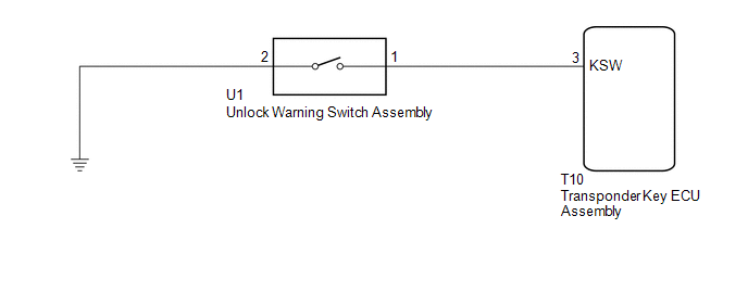
CHECK HARNESS AND CONNECTOR (TRANSPONDER KEY ECU ASSEMBLY - UNLOCK WARNING SWITCH ASSEMBLY - BODY GROUND) |
(a) Disconnect the T10 transponder key ECU assembly connector.
(b) Disconnect the U1 unlock warning switch assembly connector.
(c) Measure the resistance according to the value(s) in the table below.
Standard Resistance:
|
Tester Connection |
Condition |
Specified Condition |
|---|---|---|
|
T10-3 (KSW) - U1-1 |
Always |
Below 1 Ω |
|
T10-3 (KSW) or U1-1 - Body ground |
Always |
10 kΩ or higher |
|
U1-2 - Body ground |
Always |
Below 1 Ω |
| OK | |
REPLACE TRANSPONDER KEY ECU ASSEMBLY |
| NG | |
REPAIR OR REPLACE HARNESS OR CONNECTOR |
 Engine Immobiliser System Malfunction (B2799,B279986)
DESCRIPTION
This DTC is stored when one of the following occurs: 1) the ECM detects errors
in its own communication with the transponder key ECU assembly; 2) the ECM detects
errors in the communi ...
 Antenna Coil Open / Short (B2784)
DESCRIPTION
When an open or short circuit is detected in the antenna coil built into the
transponder key coil, the transponder key ECU assembly stores this DTC.
DTC No.
DTC D ...
Other materials:
Parts Location
PARTS LOCATION
ILLUSTRATION
ILLUSTRATION
ILLUSTRATION
ILLUSTRATION
...
Inspection
INSPECTION
PROCEDURE
1. INSPECT FUEL PUMP ASSEMBLY
(a) Measure the resistance according to the value(s) in the table below.
Standard Resistance:
Tester Connection
Condition
Specified Condition
1 - 2
20°C (68°F)
0.45 to 0 ...
Operation Check
OPERATION CHECK
1. CHECK WINDOW LOCK FUNCTION
(a) Turn the ignition switch ON.
(b) Press the window lock switch of the power window regulator master switch
assembly.
HINT:
The illumination (LED) built into the switch knob of each seat does not turn
off.
(c) Check that the power window fo ...
