Toyota Tacoma (2015-2018) Service Manual: Fuel Main Valve
Components
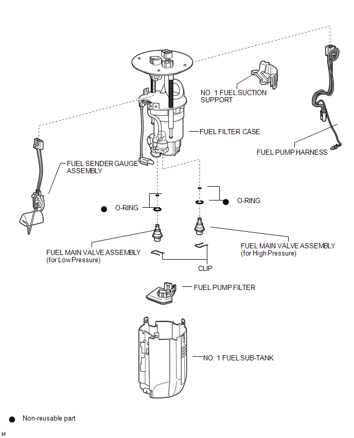
COMPONENTS
ILLUSTRATION
Removal
REMOVAL
PROCEDURE
1. REMOVE FUEL SUCTION TUBE WITH PUMP AND GAUGE ASSEMBLY
(See page .gif) )
)
2. REMOVE FUEL SENDER GAUGE ASSEMBLY
3. REMOVE NO. 1 FUEL SUB-TANK
4. REMOVE FUEL PUMP FILTER
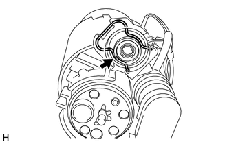
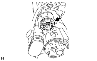
5. REMOVE FUEL MAIN VALVE ASSEMBLY
(a) Remove the fuel main valve assembly (for High Pressure).
|
(1) Remove the clip from the fuel filter case. |
|
|
(2) Using a screwdriver, remove the fuel main valve assembly from the fuel filter case. NOTICE: Do not damage the fuel filter case. |
|
(3) Remove the 2 O-rings from the fuel main valve assembly.
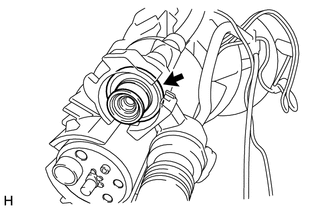
(b) Remove the fuel main valve assembly (for Low Pressure).
|
(1) Remove the clip from the fuel filter case. |
|
|
(2) Using a screwdriver, remove the fuel main valve assembly from the fuel filter case. NOTICE: Do not damage the fuel filter case. |
|
(3) Remove the 2 O-rings from the fuel main valve assembly.
Installation
INSTALLATION
PROCEDURE
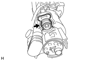
1. INSTALL FUEL MAIN VALVE ASSEMBLY
(a) Apply gasoline to 2 new O-rings. Then install the 2 O-rings to the fuel main valve assembly (for Low Pressure).
(b) Apply gasoline to 2 new O-rings. Then install the 2 O-rings to the fuel main valve assembly (for High Pressure).
(c) Install the 2 fuel main valve assemblies to the fuel filter case.
NOTICE:
- When installing the O-rings, make sure they do not become pinched or cut.
- The fuel main valve assembly (for Low Pressure) and fuel main valve assembly (for High Pressure) have identification marks (part numbers). If the parts are installed in the wrong location, the engine may stall. Therefore, make sure to install the parts in the correct location.
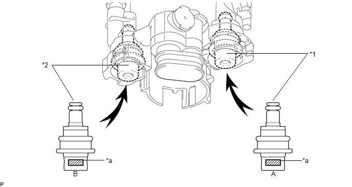 Text in Illustration
|
*1 |
Fuel Main Valve Assembly (for Low Pressure) |
*2 |
Fuel Main Valve Assembly (for High Pressure) |
|
*a |
Identification Mark (Part Number) |
- |
- |
|
A |
Fuel Main Valve Assembly (for Low Pressure) |
23070-31*** |
|
B |
Fuel Main Valve Assembly (for High Pressure) |
23070-36*** |
(d) Install the 2 clips to the fuel filter case.
2. INSTALL FUEL PUMP FILTER
.gif)
3. INSTALL NO. 1 FUEL SUB-TANK
4. INSTALL FUEL SENDER GAUGE ASSEMBLY
5. INSTALL FUEL SUCTION TUBE WITH PUMP AND GAUGE ASSEMBLY
 Installation
INSTALLATION
CAUTION / NOTICE / HINT
HINT:
Perform "Inspection After Repairs" after replacing the fuel injector assembly
(See page ).
PROCEDURE
1. INSTALL FUEL INJECTOR ASSEMBLY
HIN ...
 Fuel Pressure Sensor
Components
COMPONENTS
ILLUSTRATION
Inspection
INSPECTION
PROCEDURE
1. INSPECT FUEL DELIVERY PIPE SUB-ASSEMBLY (FUEL PRESSURE SENSOR)
NOTICE:
Do not remove the fuel pressure senso ...
Other materials:
Diagnosis System
DIAGNOSIS SYSTEM
1. DIAGNOSIS
(a) If the skid control ECU (master cylinder solenoid) detects a malfunction,
the ABS and/or BRAKE warning lights and the slip indicator lights come on in accordance
with the trouble area to warn the driver.
HINT:
The DTCs are simultaneously stored in th ...
Air Inlet Control Servo Motor
Inspection
INSPECTION
PROCEDURE
1. INSPECT AIR INLET CONTROL SERVO MOTOR
(a) Inspect the servo motor operation.
(1) Connect the positive (+) lead from the battery to terminal 1 (FRS)
and negative (-) lead to terminals 2 (REC), then check that the shaft rotates
clockwise s ...
Removal
REMOVAL
PROCEDURE
1. REMOVE NO. 2 ENGINE UNDER COVER SUB-ASSEMBLY (w/ Off Road Package)
2. REMOVE NO. 1 ENGINE UNDER COVER SUB-ASSEMBLY
3. REMOVE FAN AND GENERATOR V BELT
4. DRAIN POWER STEERING FLUID
5. REMOVE FRONT FENDER APRON UPPER SEAL RH
6. DISCONNECT NO. 1 OIL RESERVOIR TO PUMP ...
