Toyota Tacoma (2015-2018) Service Manual: Inspection
INSPECTION
PROCEDURE
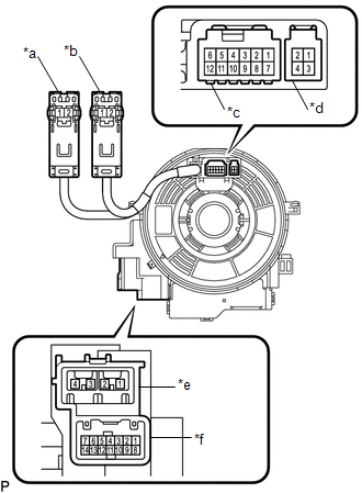
1. REMOVE SPIRAL CABLE SUB-ASSEMBLY WITH SENSOR
(a) If there are any defects as mentioned below, replace the spiral cable sub-assembly with a new one:
Scratches, cracks, dents or chips on the connector or the spiral cable sub-assembly.
|
(b) Inspect the spiral cable sub-assembly. (1) Set the spiral cable in the center, and measure the resistance in each position where the spiral cable is turned 2.5 times clockwise and counterclockwise. (2) Turn the spiral cable 2.5 times clockwise from its original position and measure the resistance while turning it 5 times counterclockwise. Text in Illustration
Standard resistance:
NOTICE: As the spiral cable sub-assembly may break, do not rotate the spiral cable sub-assembly more than the specified amount. |
|
 Removal
REMOVAL
PROCEDURE
1. REMOVE STEERING PAD
(See page
)
2. REMOVE STEERING WHEEL ASSEMBLY
3. REMOVE LOWER STEERING COLUMN COVER
4. REMOVE UPPER STEERING COLUMN COVER
5. REMOVE SPIR ...
 Installation
INSTALLATION
PROCEDURE
1. INSTALL SPIRAL CABLE SUB-ASSEMBLY WITH SENSOR
(a) Check that the ignition switch is OFF.
(b) Check that the batt ...
Other materials:
Initialization
INITIALIZATION
1. PROCEDURES NECESSARY WHEN BATTERY TEMINAL IS DISCONNECTED/RECONNECTED
Necessary Procedure
Effect/Inoperative Function when Necessary Procedures are not Performed
Link
Perform steering sensor zero point calibration
Lane ...
Brake Switch "A" Signal Compare Failure (P057162)
DESCRIPTION
When the brake pedal is depressed, the stop light switch assembly sends a signal
to the ECM. When the ECM receives this signal, it cancels the dynamic radar cruise
control. The fail-safe function operates to enable normal driving even if there
is a malfunction in the stop light si ...
System Description
SYSTEM DESCRIPTION
1. WIRELESS DOOR LOCK CONTROL SYSTEM
The wireless door lock control system can be used to lock and unlock all doors
from a distance. The system is controlled by an electrical key transmitter sub-assembly
which sends radio waves to the door control receiver. The certification ...
