Toyota Tacoma (2015-2018) Service Manual: Inspection
INSPECTION
PROCEDURE
1. INSPECT AIR CONDITIONING CONTROL ASSEMBLY
|
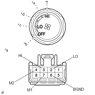
(a) Check the blower switch resistance. (1) Measure the resistance according to the value(s) in the table below. Text in Illustration
Standard Resistance:
If the result is not as specified, replace the air conditioning control assembly. |
|
|
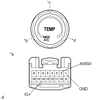
(b) Check the operation. (1) Apply battery voltage across terminals 14 (IG+) and 1 (GND). (2) Connect the positive (+) tester probe of a voltmeter to terminal 2 (AMSW) and negative (-) tester probe to terminal 1 (GND), then check the voltage. Text in Illustration
Standard Voltage:
If the result is not as specified, replace the air conditioning control assembly. |
|
|
(c) Check the operation. (1) Apply battery voltage across terminals 14 (IG+) and 1 (GND). (2) Connect the positive (+) tester probe of a voltmeter to terminal 3 (MSET) and negative (-) tester probe to terminal 1 (GND), then check the voltage. Text in Illustration
Standard Voltage:
If the result is not as specified, replace the air conditioning control assembly. |
|
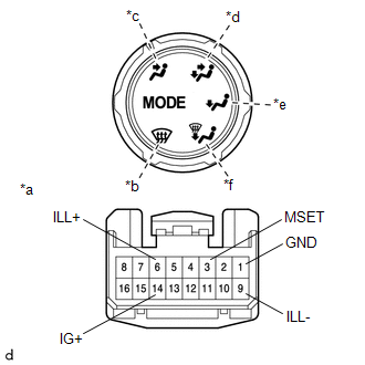
(d) Inspect the illumination.
(1) Connect the positive (+) lead to terminal 6 (ILL+) and negative (-) lead to terminal 9 (ILL-), and check that the illuminations comes on.
OK:
Illuminations comes on.
If the result is not as specified, replace the air conditioning control assembly.
 Components
COMPONENTS
ILLUSTRATION
*A
w/o Navigation System
*B
w/ Navigation System
*C
for Double Cab
*D
for Acce ...
 Installation
INSTALLATION
PROCEDURE
1. INSTALL TRANSFER POSITION SWITCH (for 4WD)
Click here
2. INSTALL ENGINE SWITCH
Click here
3. INSTALL AIR CONDITIONING CONTROL ASSEMBLY
(a) Connect the connectors.
...
Other materials:
Open or Short Circuit in Back Camera Signal (C1622)
DESCRIPTION
This DTC is stored if the radio and display receiver assembly*1 or navigation
receiver assembly*2 judges as a result of its self check that the signals or signal
lines between the radio and display receiver assembly*1 or navigation receiver assembly*2
and the rear television camer ...
Cruise Control Input Processor (P160700)
DESCRIPTION
The ECM continuously monitors its main and sub CPUs. This self-check ensures
that the ECM is functioning properly. If outputs from the CPUs are different and
deviate from the standard, the ECM will illuminate the MIL and store the DTC.
DTC No.
Detection Item
...
Removal
REMOVAL
CAUTION / NOTICE / HINT
CAUTION:
Some of these service operations affect the SRS airbag system. Read the precautionary
notices concerning the SRS airbag system before servicing.
Click here
PROCEDURE
1. PRECAUTION
NOTICE:
After turning the ignition switch off, waiting time may be ...
