Toyota Tacoma (2015-2018) Service Manual: Terminals Of Ecm
TERMINALS OF ECM
HINT:
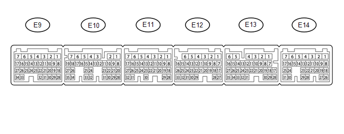
The standard normal voltage between each pair of ECM terminals is shown in the table below. The appropriate conditions for checking each pair of terminals are also indicated. The result of checks should be compared with the standard normal voltage for that pair of terminals, displayed in the Specified Condition column. The illustration above can be used as a reference to identify the ECM terminal locations.
|
Terminal No. (Symbol) |
Wiring Color |
Terminal Description |
Condition |
Specified Condition |
|---|---|---|---|---|
|
E14-2 (BATT) - E11-1 (E1) |
L - W-B |
Battery (for measuring battery voltage and for ECM memory) |
Always |
11 to 14 V |
|
E12-6 (+BM) - E11-1 (E1) |
GR - W-B |
Power source of throttle actuator |
Always |
11 to 14 V |
|
E14-3 (+B) - E11-1 (E1) |
B - W-B |
Power source of ECM |
Ignition switch ON |
11 to 14 V |
|
E14-4 (+B2) - E11-1 (E1) |
B - W-B |
Power source of ECM |
Ignition switch ON |
11 to 14 V |
|
E14-25 (MREL) - E11-1 (E1) |
GR - W-B |
EFI-MAIN NO. 1 relay operation signal |
Ignition switch ON |
11 to 14 V |
|
E9-26 (VCNE) - E11-1 (E1) |
R - W-B |
Power source of crankshaft position sensor (specific voltage) |
Ignition switch ON |
4.5 to 5.5 V |
|
E9-25 (NE+) - E9-33 (NE-) |
B - G |
Crankshaft position sensor |
Idling |
Pulse generation |
|
E13-24 (SPD) - E11-1 (E1) |
R - W-B |
Vehicle speed signal from combination meter assembly |
Driving at 20 km/h (12 mph) |
Pulse generation |
|
E11-1 (E1) - Body ground |
W-B - Body ground |
Ground circuit of ECM |
Always |
Below 1 Ω |
 Diagnosis System
DIAGNOSIS SYSTEM
1. DESCRIPTION
(a) To check DTCs, connect the Techstream to the Data Link Connector 3 (DLC3)
of the vehicle. The Techstream displays DTCs and freeze frame data. The DTCs and
fre ...
 Check Mode Procedure
CHECK MODE PROCEDURE
1. DESCRIPTION
Check mode has a higher sensitivity to malfunctions and can detect malfunctions
that cannot be detected in normal mode. Check mode can also detect all of the ma ...
Other materials:
Installation
INSTALLATION
CAUTION / NOTICE / HINT
HINT:
Use the same procedure for both the LH and RH sides.
The procedure described below is for the LH side.
PROCEDURE
1. INSTALL FOG LAMP ASSEMBLY
(a) Engage the 2 guides to install the fog light assembly.
(b) Install the screw.
(c) Con ...
Image from Camera for Rear View Monitor is Abnormal
DESCRIPTION
The display signal of the rear television camera assembly is transmitted to the
radio and display receiver assembly*1 or navigation receiver assembly*2.
*1: w/o Navigation System
*2: w/ Navigation System
WIRING DIAGRAM
PROCEDURE
1.
CONFIRM ...
Terminals Of Ecu
TERMINALS OF ECU
1. REAR TELEVISION CAMERA ASSEMBLY
(a) Disconnect the T22 television camera assembly connector.
(b) Measure the voltage and resistance according to the value(s) in the table
below.
Terminal No. (Symbol)
Wiring Color
Terminal Description
...
