Toyota Tacoma (2015-2018) Service Manual: Components
COMPONENTS
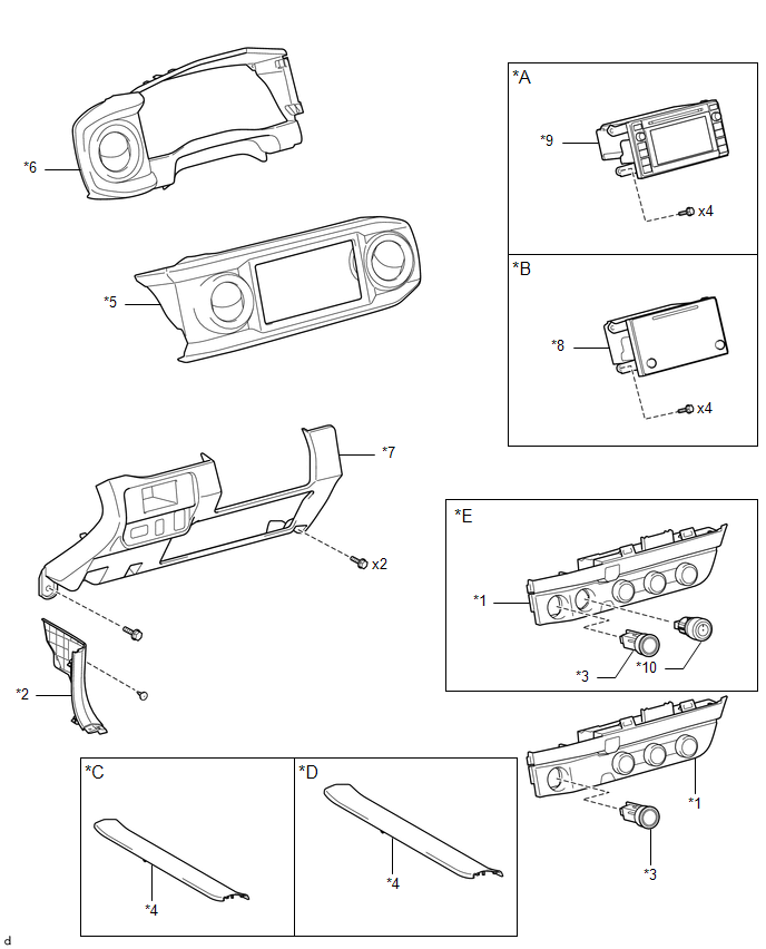
ILLUSTRATION
|
*A |
w/o Navigation System |
*B |
w/ Navigation System |
|
*C |
for Double Cab |
*D |
for Acces Cab |
|
*E |
for 4WD |
- |
- |
|
*1 |
AIR CONDITIONING CONTROL ASSEMBLY |
*2 |
COWL SIDE TRIM BOARD LH |
|
*3 |
ENGINE SWITCH |
*4 |
FRONT DOOR SCUFF PLATE LH |
|
*5 |
INSTRUMENT CLUSTER CENTER FINISH PANEL SUB-ASSEMBLY |
*6 |
INSTRUMENT CLUSTER FINISH PANEL ASSEMBLY |
|
*7 |
INSTRUMENT PANEL LOWER FINISH PANEL SUB-ASSEMBLY |
*8 |
NAVIGATION RECEIVER ASSEMBLY WITH BRACKET |
|
*9 |
RADIO AND DISPLAY RECEIVER ASSEMBLY WITH BRACKET |
*10 |
TRANSFER POSITION SWITCH |

 Inspection
INSPECTION
PROCEDURE
1. INSPECT AIR CONDITIONING CONTROL ASSEMBLY
(a) Check the blower switch resistance.
(1) Measure the resistance according to the value(s) in the table below.
T ...
Other materials:
Operation Check
OPERATION CHECK
INPUT SIGNAL CHECK
*a
+RES
*b
-SET
*c
ON-OFF
*d
CANCEL
(a) Connect the Techstream to the DLC3.
(b) Check the cruise control main switch using the Data List functio ...
Disassembly
DISASSEMBLY
PROCEDURE
1. REMOVE TELEPHONE MICROPHONE ASSEMBLY
Click here
2. REMOVE MICROPHONE CASE
(a) w/o Sliding Roof:
(1) Disengage the claw and guide to remove the microphone case.
(b) w/ Sliding Roof:
(1) Disengage th ...
Components
COMPONENTS
ILLUSTRATION
ILLUSTRATION
ILLUSTRATION
ILLUSTRATION
ILLUSTRATION
...
