Toyota Tacoma (2015-2018) Service Manual: Inspection
INSPECTION
PROCEDURE
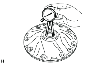
1. INSPECT FRONT OIL PUMP BODY SUB-ASSEMBLY
|
(a) Using a dial indicator, measure the inside diameter of the front oil pump body sub-assembly bushing. Maximum inside diameter: 38.138 mm (1.50 in.) If the inside diameter is more than the maximum inside diameter, replace the front oil pump body sub-assembly. |
|
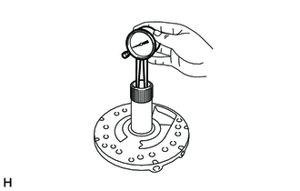
2. INSPECT STATOR SHAFT ASSEMBLY
|
(a) Using a dial indicator, measure the inside diameter of the stator shaft assembly bushing. Maximum inside diameter: 22.227 mm (0.875 in.) If the inside diameter is more than the maximum inside diameter, replace the stator shaft assembly. |
|
3. INSPECT CLEARANCE OF OIL PUMP ASSEMBLY
|
(a) Push the front oil pump driven gear to one side of the front oil pump body sub-assembly. |
|
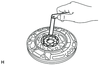
(b) Using a feeler gauge, measure the clearance.
Standard body clearance:
0.10 to 0.17 mm (0.00394 to 0.00669 in.)
If the body clearance is more than the standard clearance, check the front oil pump drive gear, front oil pump driven gear and front oil pump body sub-assembly.
|
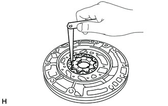
(c) Using a feeler gauge, measure the clearance between the front oil pump driven gear teeth and the front oil pump drive gear teeth. Standard tip clearance: 0.07 to 0.15 mm (0.00276 to 0.00590 in.) If the tip clearance is more than the standard clearance, check the front oil pump drive gear, front oil pump driven gear and front oil pump body sub-assembly. |
|
|
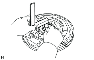
(d) Using a steel straightedge and a feeler gauge, measure the side clearance of both gears. Standard side clearance: 0.03 to 0.05 mm (0.00118 to 0.00196 in.) If the side clearance is more than the standard thickness, check the front oil pump drive gear, front oil pump driven gear and front oil pump body sub-assembly. |
|
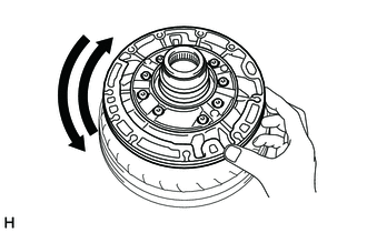
4. INSPECT OIL PUMP DRIVE GEAR ROTATION
(a) Install the oil pump assembly to the torque converter assembly.
|
(b) Check that the front oil pump drive gear rotates smoothly. |
|
(c) Remove the oil pump assembly from the torque converter assembly.
 Disassembly
DISASSEMBLY
PROCEDURE
1. REMOVE FRONT OIL PUMP BODY O-RING
(a) Remove the front oil pump body O-ring from the oil pump assembly.
2. SECURE OIL ...
 Reassembly
REASSEMBLY
PROCEDURE
1. INSTALL FRONT OIL PUMP OIL SEAL
(a) Using SST and a hammer, install a new front oil pump oil seal to
the front oil pump body sub-assembly.
SST: 09350-30020 ...
Other materials:
Diagnostic Trouble Code Chart
DIAGNOSTIC TROUBLE CODE CHART
Manual Transmission System
DTC Code
Detection Item
MIL
Memory
See page
P03352A
Crankshaft Position Sensor "A" Signal Stuck in Range
Does not come on
DTC ...
Steering Angle Sensor (C1A47)
DESCRIPTION
The blind spot monitor sensor receives steering angle signals from the spiral
cable with sensor sub-assembly via CAN communication.
DTC Code
DTC Detection Condition
Trouble Area
C1A47
A fail flag is transmitted from the ste ...
Vehicle data recordings
Your Toyota is equipped with several sophisticated computers that will record
certain data, such as: ŌĆó Engine speed
ŌĆó Accelerator status
ŌĆó Brake status
ŌĆó Vehicle speed
ŌĆó Shift position (except manual transmission)
The recorded data varies according to the vehicle grade level and opt ...
