Toyota Tacoma (2015-2018) Service Manual: Reassembly
REASSEMBLY
PROCEDURE
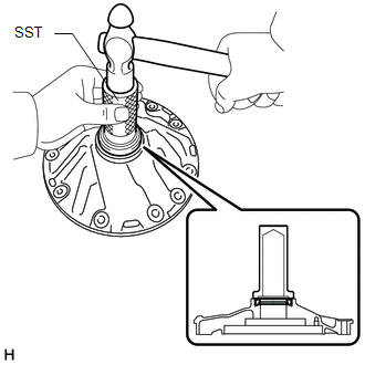
1. INSTALL FRONT OIL PUMP OIL SEAL
|
(a) Using SST and a hammer, install a new front oil pump oil seal to the front oil pump body sub-assembly. SST: 09350-30020 09351-32140 Standard depth: -0.3 to 0.3 mm (-0.0118 to 0.0118 in.) |
|
(b) Coat the lip of the front oil pump oil seal with MP grease.
2. SECURE FRONT OIL PUMP BODY SUB-ASSEMBLY
(a) Place the front oil pump body sub-assembly on the torque converter assembly.
3. INSTALL FRONT OIL PUMP DRIVEN GEAR
|
(a) Coat the front oil pump driven gear with ATF and install it to the front oil pump body sub-assembly. |
|
.png)
4. INSTALL FRONT OIL PUMP DRIVE GEAR
|
(a) Coat the front oil pump drive gear with ATF and install it to the front oil pump body sub-assembly. |
|
.png)
5. INSTALL STATOR SHAFT ASSEMBLY
|
(a) Align the bolt holes of the stator shaft assembly with the bolt holes of the front oil pump body sub-assembly and install the stator shaft assembly to the front oil pump body sub-assembly. |
|
.png)
(b) Using a T30 "TORX" socket wrench, install the 7 screws.
Torque:
11 N·m {110 kgf·cm, 8 ft·lbf}
6. INSTALL FRONT OIL PUMP PLATE
|
(a) Using a T30 "TORX" socket wrench, install the front oil pump plate with the 3 screws. Torque: 11 N·m {110 kgf·cm, 8 ft·lbf} |
|
.png)
7. INSPECT OIL PUMP DRIVE GEAR ROTATION
.gif)
8. INSTALL CLUTCH DRUM OIL SEAL RING
|
(a) Coat 2 new clutch drum oil seal rings with ATF and install them to the oil pump assembly NOTICE:
|
|
.png)
9. INSTALL FRONT OIL PUMP BODY O-RING
|
(a) Coat a new front oil pump body O-ring with ATF and install it to the oil pump assembly. |
|
.png)
 Inspection
INSPECTION
PROCEDURE
1. INSPECT FRONT OIL PUMP BODY SUB-ASSEMBLY
(a) Using a dial indicator, measure the inside diameter of the front
oil pump body sub-assembly bushing.
Maximum i ...

Other materials:
Diagnosis System
DIAGNOSIS SYSTEM
CHECK DLC3
(a) Check the DLC3.
Click here
FUNCTION OF WARNING INDICATOR AND MESSAGE
(a) If the lane departure alert system is not functioning properly, the driver
is warned by the lane departure alert indicator and multi-information display warning
message on the combinat ...
Pressure Control Solenoid "C" Performance (Shift Solenoid Valve SL3) (P0796)
SYSTEM DESCRIPTION
The ECM uses the vehicle speed signal and signals from the transmission revolution
sensors (NT, SP2) to detect the actual gear (1st, 2nd, 3rd, 4th, 5th or 6th gear).
The ECM compares the actual gear with the shift schedule in the ECM memory to
detect mechanical problems of t ...
System Voltage Circuit Short to Ground or Open (P056014)
DESCRIPTION
The battery supplies power to the ECM even when the ignition switch is off. This
power allows the ECM to store data such as DTC history, freeze frame data and fuel
trim values. If the battery voltage falls below a minimum level, the ECM data is
cleared and the ECM determines that ...
