Toyota Tacoma (2015-2018) Service Manual: Disassembly
DISASSEMBLY
PROCEDURE
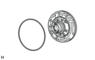
1. REMOVE FRONT OIL PUMP BODY O-RING
|
(a) Remove the front oil pump body O-ring from the oil pump assembly. |
|
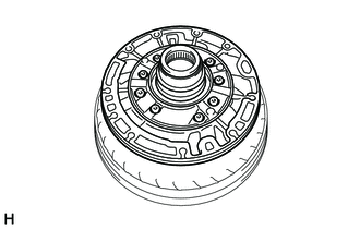
2. SECURE OIL PUMP ASSEMBLY
|
(a) Place the oil pump assembly on the torque converter assembly. |
|
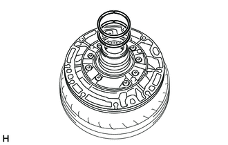
3. REMOVE CLUTCH DRUM OIL SEAL RING
|
(a) Remove the 2 clutch drum oil seal rings from the oil pump assembly. |
|
4. INSPECT FRONT OIL PUMP DRIVE GEAR ROTATION
.gif)
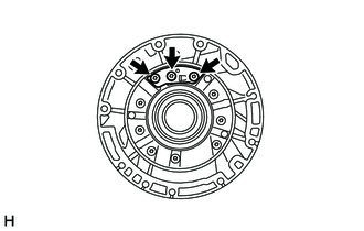
5. REMOVE FRONT OIL PUMP PLATE
|
(a) Using a T30 "TORX" socket wrench, remove the 3 screws and front oil pump plate from the oil pump assembly. |
|
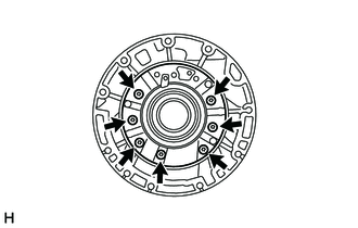
6. REMOVE STATOR SHAFT ASSEMBLY
|
(a) Using a T30 "TORX" socket wrench, remove the 7 screws and stator shaft assembly from the front oil pump body sub-assembly. |
|
7. INSPECT STATOR SHAFT ASSEMBLY
8. INSPECT CLEARANCE OF OIL PUMP ASSEMBLY
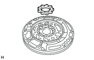
9. REMOVE FRONT OIL PUMP DRIVE GEAR
|
(a) Remove the front oil pump drive gear from the front oil pump body sub-assembly. |
|
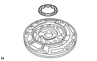
10. REMOVE FRONT OIL PUMP DRIVEN GEAR
|
(a) Remove the front oil pump driven gear from the front oil pump body sub-assembly. |
|
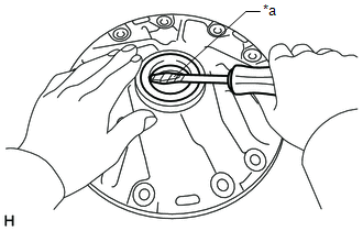
11. REMOVE FRONT OIL PUMP OIL SEAL
|
(a) Using a screwdriver, remove the front oil pump oil seal from the front oil pump body sub-assembly. Text in Illustration
NOTICE: Do not damage the bushing or front oil pump body sub-assembly. HINT: Tape the screwdriver tip before use. |
|
12. INSPECT FRONT OIL PUMP BODY SUB-ASSEMBLY
 Components
COMPONENTS
ILLUSTRATION
...
 Inspection
INSPECTION
PROCEDURE
1. INSPECT FRONT OIL PUMP BODY SUB-ASSEMBLY
(a) Using a dial indicator, measure the inside diameter of the front
oil pump body sub-assembly bushing.
Maximum i ...
Other materials:
Reassembly
REASSEMBLY
PROCEDURE
1. INSTALL NO. 2 ANTENNA CORD SUB-ASSEMBLY
(a) Using hot-melt glue, install the No. 2 antenna cord sub-assembly as shown
in the illustration.
2. INSTALL NO. 1 ROOF WIRE (w/ Vanity Light)
(a) w/ EC Mirror:
(1) Align the aiming tape as shown in the illustration.
...
Installation
INSTALLATION
CAUTION / NOTICE / HINT
NOTICE:
Always use a new grommet and valve core when installing the tire pressure
warning valve and transmitter.
Check that the washer and nut are not damaged, and replace them if necessary.
If installing a new tire pressure warning valv ...
Problem Symptoms Table
PROBLEM SYMPTOMS TABLE
HINT:
Use the table below to help determine the cause of problem symptoms.
If multiple suspected areas are listed, the potential causes of the symptoms
are listed in order of probability in the "Suspected Area" column of the
table. Check each sy ...
