Toyota Tacoma (2015-2018) Service Manual: Evaporator Temperature Sensor Circuit (B1413)
DESCRIPTION
The cooler thermistor sensor (evaporator temperature sensor) is installed on the evaporator in the air conditioner unit to detect the temperature of the cooled air that has passed through the evaporator and is used to control the air conditioning. It sends signals to the air conditioning amplifier assembly. The resistance of the cooler thermistor sensor (evaporator temperature sensor) changes in accordance with the temperature of the cooled air that has passed through the evaporator. As the temperature decreases, the resistance increases. As the temperature increases, the resistance decreases.
The air conditioning amplifier assembly applies voltage (5 V) to the cooler thermistor sensor (evaporator temperature sensor) and reads voltage changes as the resistance of the cooler thermistor sensor (evaporator temperature sensor) changes. This sensor is used for frost prevention.
|
DTC No. |
DTC Detection Condition |
Trouble Area |
|---|---|---|
|
B1413 |
Open or short in cooler thermistor sensor (evaporator temperature sensor) circuit |
|
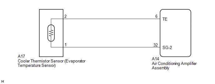
WIRING DIAGRAM
PROCEDURE
|
1. |
READ VALUE USING TECHSTREAM |
(a) Connect the Techstream to the DLC3.
(b) Turn the ignition switch to ON.
(c) Turn the Techstream on.
(d) Enter the following menus: Body Electrical / Air Conditioner / Data List.
(e) Check the value(s) by referring to the table below.
Air Conditioner|
Tester Display |
Measurement Item/Range |
Normal Condition |
Diagnostic Note |
|---|---|---|---|
|
Evaporator Fin Thermistor |
Cooler thermistor sensor (Evaporator temperature sensor) / Min.: -29.70°C (-21.46°F) Max.: 59.55°C (139.19°F) |
Actual evaporator temperature displayed |
- |
OK:
The display is as specified in the Normal Condition column.
|
Result |
Proceed to |
|---|---|
|
NG |
A |
|
OK (When troubleshooting according to Problem Symptoms Table) |
B |
|
OK (When troubleshooting according to the DTC) |
C |
| B | .gif) |
PROCEED TO NEXT SUSPECTED AREA SHOWN IN PROBLEM SYMPTOMS TABLE |
| C | |
REPLACE AIR CONDITIONING AMPLIFIER ASSEMBLY |
|
.gif)
|
2. |
INSPECT COOLER THERMISTOR SENSOR (EVAPORATOR TEMPERATURE SENSOR) |
(a) Remove the cooler thermistor sensor (evaporator temperature sensor) (See
page .gif) ).
).
(b) Inspect the cooler thermistor sensor (evaporator temperature sensor) (See
page ).
| NG | |
REPLACE COOLER THERMISTOR SENSOR (EVAPORATOR TEMPERATURE SENSOR) |
|
|
3. |
CHECK HARNESS AND CONNECTOR (COOLER THERMISTOR SENSOR (EVAPORATOR TEMPERATURE SENSOR) - AIR CONDITIONING AMPLIFIER ASSEMBLY) |
(a) Disconnect the A17 cooler thermistor sensor (evaporator temperature sensor) connector.
(b) Disconnect the A14 air conditioning amplifier assembly connector.
(c) Measure the resistance according to the value(s) in the table below.
Standard Resistance:
|
Tester Connection |
Condition |
Specified Condition |
|---|---|---|
|
A14-6 (TE) - A17-2 |
Always |
Below 1 Ω |
|
A14-32 (SG-2) - A17-1 |
Always |
Below 1 Ω |
|
A14-6 (TE) or A17-2 - Body ground |
Always |
10 kΩ or higher |
|
A14-32 (SG-2) or A17-1 - Body ground |
Always |
10 kΩ or higher |
| OK | |
REPLACE AIR CONDITIONING AMPLIFIER ASSEMBLY |
| NG | |
REPAIR OR REPLACE HARNESS OR CONNECTOR |
 Air Conditioning Compressor Magnetic Clutch Circuit
DESCRIPTION
When the air conditioning amplifier assembly is turned on, a magnetic clutch
on signal is sent from the MGC terminal of the air conditioning amplifier assembly.
Then, the MG CLT relay ...
 Compressor Lock Sensor Circuit (B1422)
SYSTEM DESCRIPTION
The ECM sends the engine speed signal to the air conditioning amplifier assembly
via CAN communication.
The air conditioning amplifier assembly reads the difference between comp ...
Other materials:
Sliding Roof does not Move by Operating Sliding Roof Control Switch
DESCRIPTION
The sliding roof ECU (sliding roof drive gear sub-assembly) receives slide and
tilt signals when the sliding roof switch is operated and drives its built-in motor.
WIRING DIAGRAM
CAUTION / NOTICE / HINT
NOTICE:
Inspect the fuses for circuits related to this system before ...
Precaution
PRECAUTION
1. IGNITION SWITCH EXPRESSION
(a) The type of ignition switch used on this model differs depending on the specifications
of the vehicle. The expressions listed in the table below are used in this section.
Expression
Ignition Switch (Position)
Engine S ...
Installation
INSTALLATION
PROCEDURE
1. INSTALL FRONT DISC
(a) Align the matchmarks of the front disc and the front axle hub and
install the front disc.
Text in Illustration
*a
Matchmark
HINT:
When replacing the disc with a new one, se ...
