Toyota Tacoma (2015-2018) Service Manual: Dtc Check / Clear
DTC CHECK / CLEAR
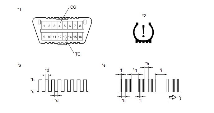
1. CHECK DTC (for TIRE PRESSURE WARNING ECU AND RECEIVER) (USING TECHSTREAM)
(a) Turn the ignition switch off.
(b) Connect the Techstream to the DLC3.
(c) Turn the ignition switch to ON.
(d) Turn the Techstream on.
(e) Enter the following menus: Chassis / Tire Pressure Monitor / Trouble Codes.
(f) Read the DTCs.
2. CHECK DTC (for TIRE PRESSURE WARNING ECU AND RECEIVER) (USING SST CHECK WIRE)
(a) Turn the ignition switch off.
 Text in Illustration
|
*1 |
DLC3 |
*2 |
Tire Pressure Warning Light |
|
*a |
Normal System Code |
*b |
ON |
|
*c |
OFF |
*d |
0.25 sec. |
|
*e |
Code 13 and 33 |
*f |
0.5 sec. |
|
*g |
2.5 sec. |
*h |
1.5 sec. |
|
*i |
4.5 sec. |
*j |
Repeat |
(b) Using SST, connect terminals 13 (TC) and 4 (CG) of the DLC3.
SST: 09843-18040
(c) Turn the ignition switch to ON.
(d) Read and record any DTCs indicated by the tire pressure warning light in the combination meter assembly. Refer to the illustration for examples of a normal system code and codes 13 and 33.
HINT:
- If the tire pressure warning light does not indicate any DTCs or the
normal system code, inspect the tire pressure warning light circuit or TC
and CG terminal circuit.
Trouble Area
Link
Tire pressure warning light circuit
.gif)
TC and CG terminal circuit
- If 2 or more malfunctions are indicated at the same time, the lowest numbered DTC is displayed first.
(e) Refer to Diagnostic Trouble Code Chart for DTC information (See page
).
(f) After completing the check, turn the ignition switch off and remove SST from the DLC3.
3. CHECK DTC (for MAIN BODY ECU (MULTIPLEX NETWORK BODY ECU))
(a) Turn the ignition switch off.
(b) Connect the Techstream to the DLC3.
(c) Turn the ignition switch to ON.
(d) Turn the Techstream on.
(e) Enter the following menus: Body Electrical / Main Body / Trouble Codes.
(f) Read the DTCs.
4. CLEAR DTC (for TIRE PRESSURE WARNING ECU AND RECEIVER)
HINT:
After repairing the malfunctions, clear the DTCs.
(a) Turn the ignition switch off.
(b) Connect the Techstream to the DLC3.
(c) Turn the ignition switch to ON.
(d) Turn the Techstream on.
(e) Enter the following menus: Chassis / Tire Pressure Monitor / Trouble Codes.
(f) Clear the DTCs following the prompts on the Techstream screen.
HINT:
Refer to the Techstream operator's manual for further details.
5. CLEAR DTC (for MAIN BODY ECU (MULTIPLEX NETWORK BODY ECU))
HINT:
After repairing the malfunctions, clear the DTCs.
(a) Turn the ignition switch off.
(b) Connect the Techstream to the DLC3.
(c) Turn the ignition switch to ON.
(d) Turn the Techstream on.
(e) Enter the following menus: Body Electrical / Main Body / Trouble Codes.
(f) Clear the DTCs following the prompts on the Techstream screen.
HINT:
Refer to the Techstream operator's manual for further details.
 Data List / Active Test
DATA LIST / ACTIVE TEST
1. READ DATA LIST
HINT:
Using the Techstream to read the Data List allows the values or states of switches,
sensors, actuators and other items to be read without removing ...
 Transmitter ID not Received in Main Mode (C2126/26)
DESCRIPTION
After all transmitter IDs are registered, DTC C2126/26 is stored in the tire
pressure warning ECU and receiver and the tire pressure warning light blinks for
1 minute and then illumin ...
Other materials:
Wheels
If a wheel is bent, cracked or heavily corroded, it should be replaced.
Otherwise, the tire may separate from the wheel or cause loss of handling control.
■ Wheel selection
When replacing wheels, care should be taken to ensure that they are equivalent
to those removed in load capacity, di ...
SM Solenoid Circuit (C1225-C1228,C1468,C1469,C146A,C146B)
DESCRIPTION
The solenoid goes on when signals are received from the skid control ECU (master
cylinder solenoid) and controls the pressure action on the wheel cylinders thus
controlling the braking force.
DTC No.
DTC Detecting Conditions
Trouble Areas
...
Automatic High Beam System (B124B)
DESCRIPTION
The main body ECU (multiplex network body ECU) determines the status of the automatic
high beam system based on the automatic high beam system signal from the forward
recognition camera.
DTC No.
Detection Item
DTC Detection Condition
Trou ...
