Toyota Tacoma (2015-2018) Service Manual: Automatic High Beam System (B124B)
DESCRIPTION
The main body ECU (multiplex network body ECU) determines the status of the automatic high beam system based on the automatic high beam system signal from the forward recognition camera.
|
DTC No. |
Detection Item |
DTC Detection Condition |
Trouble Area |
|---|---|---|---|
|
B124B |
Automatic High Beam System |
Malfunction in automatic high beam system |
|
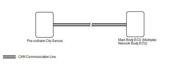
WIRING DIAGRAM
CAUTION / NOTICE / HINT
NOTICE:
First perform the communication function inspections in How to Proceed with Troubleshooting to confirm that there are no CAN communication malfunctions before troubleshooting this symptom
Click here .gif)
HINT:
If the forward recognition camera stores a DTC for a malfunction of any of the following, this DTC will be stored simultaneously.
- Speed sensor malfunction
- Yaw rate sensor malfunction
- Steering sensor malfunction
- CAN communication lost
PROCEDURE
|
1. |
CHECK FOR DTC (HEALTH CHECK) |
(a) Connect the Techstream to the DLC3.
(b) Turn the ignition switch to ON.
(c) Turn the Techstream on.
(d) Enter the following menus: System Select / Health Check.
(e) Check for DTCs.
Result|
Result |
Proceed to |
|---|---|
|
Only DTC B124B is output |
A |
|
DTC B124B is output at the same time |
B |
| B | .gif) |
GO TO OTHER DTC CHART |
|
.gif)
|
2. |
CHECK FORWARD RECOGNITION CAMERA |
(a) Check if a dynamic radar cruise control system, lane departure alert system and pre-collision system warning message are displayed on the combination meter assembly.
Click here
OK:
No dynamic radar cruise control system, lane departure alert system and pre-collision system warning messages are displayed.
|
Proceed to |
|---|
|
OK |
|
NG |
| OK | |
REPLACE MAIN BODY ECU (MULTIPLEX NETWORK BODY ECU) |
| NG | |
GO TO FORWARD RECOGNITION CAMERA SYSTEM |
 Diagnostic Trouble Code Chart
DIAGNOSTIC TROUBLE CODE CHART
HINT:
If a trouble code is displayed during the DTC check, inspect the trouble areas
listed for that code. For details of the code, refer to the "See page" ...
 Automatic High Beam Camera (B124C)
DESCRIPTION
The main body ECU (multiplex network body ECU) detects a high beam headlight
illumination request signal of the automatic high beam system from the forward recognition
camera
...
Other materials:
Removal
REMOVAL
PROCEDURE
1. REMOVE FRONT DOOR SCUFF PLATE LH (for Double Cab)
2. REMOVE FRONT DOOR SCUFF PLATE LH (for Access Cab)
3. REMOVE COWL SIDE TRIM BOARD LH
4. REMOVE INSTRUMENT CLUSTER CENTER FINISH PANEL SUB-ASSEMBLY
5. REMOVE INSTRUMENT CLUSTER FINISH PANEL ASSEMBLY
6. ...
Cargo Light Switch
Components
COMPONENTS
ILLUSTRATION
Inspection
INSPECTION
PROCEDURE
1. INSPECT DECK LIGHT SWITCH ASSEMBLY
(a) Check the resistance.
(1) Measure the resistance according to the value(s) in the table below.
Text in Illustration
*a
Compone ...
Pressure Control Solenoid "B" Electrical (Shift Solenoid Valve SL2) (P0778)
DESCRIPTION
Changing from 1st to 6th is performed by the ECM turning shift solenoid valves
SL1, SL2, SL3 and SL4 on and off. If an open or short circuit occurs in any of the
shift solenoid valves, the ECM controls the remaining normal shift solenoid valves
to allow the vehicle to be operated ...
