Toyota Tacoma (2015-2018) Service Manual: Disassembly
DISASSEMBLY
PROCEDURE
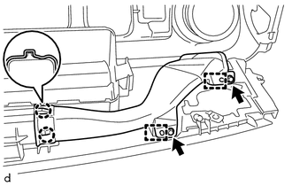
1. REMOVE NO. 1 HEATER TO REGISTER DUCT
|
(a) Remove the 2 screws <F> and screw <D>. |
|
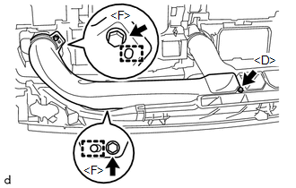
(b) Disengage the 2 guides to remove the No. 1 heater to register duct.
2. REMOVE NO. 3 HEATER TO REGISTER DUCT
|
(a) Remove the 2 screws <F> and screw <D>. |
|
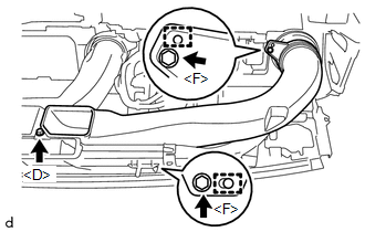
(b) Disengage the 2 guides to remove the No. 3 heater to register duct.
3. REMOVE NO. 2 HEATER TO REGISTER DUCT
|
(a) Remove the 2 screws <F> and screw <D>. |
|
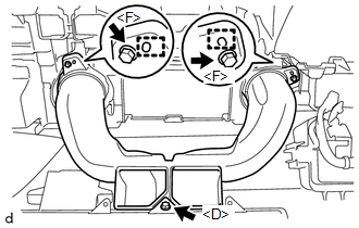
(b) Disengage the 2 guides to remove the No. 2 heater to register duct.
4. REMOVE SIDE NO. 1 DEFROSTER NOZZLE DUCT
|
(a) Remove the 2 screws <F>. |
|
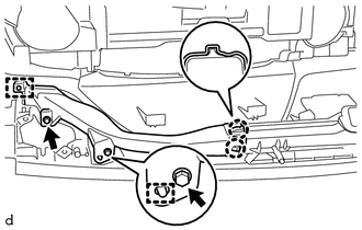
(b) Disengage the 2 guides.
(c) Disengage the 2 claws to remove the side No. 1 defroster nozzle duct.
5. REMOVE SIDE NO. 2 DEFROSTER NOZZLE DUCT
|
(a) Remove the 2 screws <F>. |
|
(b) Disengage the 2 guides.
(c) Disengage the 2 claws to remove the side No. 2 defroster nozzle duct.
6. REMOVE DEFROSTER NOZZLE ASSEMBLY
|
(a) Remove the 3 screws <F>. |
|
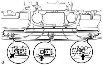
(b) Disengage the 3 guides to remove the defroster nozzle assembly.
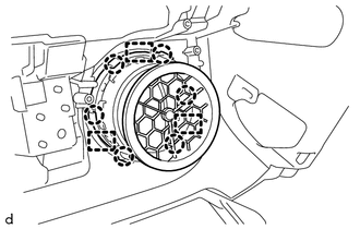
7. REMOVE NO. 1 INSTRUMENT PANEL REGISTER SUB-ASSEMBLY
|
(a) Disengage the 6 claws and 3 guides to remove the No. 1 instrument panel register sub-assembly. |
|
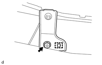
8. REMOVE NETWORK GATEWAY ECU
.gif)
9. REMOVE NAVIGATION ANTENNA ASSEMBLY (w/ Navigation System)
10. REMOVE ANTENNA CORD SUB-ASSEMBLY
11. REMOVE INSTRUMENT PANEL PASSENGER WITHOUT DOOR AIRBAG ASSEMBLY
12. REMOVE NO. 1 INSTRUMENT PANEL PIN
HINT:
Use the same procedure as for the opposite side.
|
(a) Remove the screw <F>. |
|
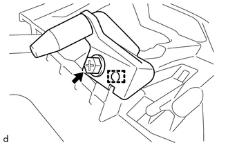
(b) Disengage the guide to remove the No. 1 instrument panel pin.
13. REMOVE NO. 1 METER HOOD RETAINER
HINT:
Use the same procedure as for the opposite side.
|
(a) Remove the screw <D>. |
|
(b) Disengage the guide to remove the No. 1 meter hood retainer.
14. REMOVE NO. 1 INSTRUMENT PANEL CUSHION
|
(a) Remove the No. 1 instrument panel cushion. |
|
15. REMOVE NO. 2 INSTRUMENT PANEL CUSHION
|
(a) Remove the No. 2 instrument panel cushion. |
|
16. REMOVE NO. 4 INSTRUMENT PANEL CUSHION
|
(a) Remove the No. 4 instrument panel cushion. |
|
17. REMOVE INSTRUMENT PANEL CUSHION
|
(a) Remove the instrument panel cushion. |
|
 Components
COMPONENTS
ILLUSTRATION
ILLUSTRATION
ILLUSTRATION
ILLUSTRATION
ILLUSTRATION
ILLUSTRATION
ILLUSTRATION
ILLUSTRATION
...
 Removal
REMOVAL
PROCEDURE
1. TABLE OF BOLT, SCREW AND NUT
HINT:
All bolts, screws and nuts relevant to installing and removing the instrument
panel are shown along with their alphabetic codes in the tab ...
Other materials:
Terminals Of Ecu
TERMINALS OF ECU
1. REAR TELEVISION CAMERA ASSEMBLY
(a) Disconnect the T22 television camera assembly connector.
(b) Measure the voltage and resistance according to the value(s) in the table
below.
Terminal No. (Symbol)
Wiring Color
Terminal Description
...
Navigation Antenna
Components
COMPONENTS
ILLUSTRATION
Installation
INSTALLATION
PROCEDURE
1. INSTALL NAVIGATION ANTENNA ASSEMBLY
(a) Install the navigation antenna assembly with the 2 screws.
(b) Engage the 2 clamps.
2. INSTALL NO. 1 HEATER TO REGISTER DUCT
(See page )
3. INSTALL INSTRUMENT PANEL SUB ...
Output Shaft
Components
COMPONENTS
ILLUSTRATION
Disassembly
DISASSEMBLY
PROCEDURE
1. REMOVE FRONT OUTPUT SHAFT BEARING
(a) Temporarily install the manual transmission output shaft rear set
nut to the output shaft.
Text in Illustration
*1
Manual ...
