Toyota Tacoma (2015-2018) Service Manual: Components
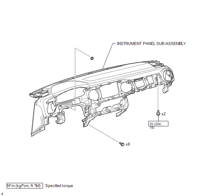
COMPONENTS
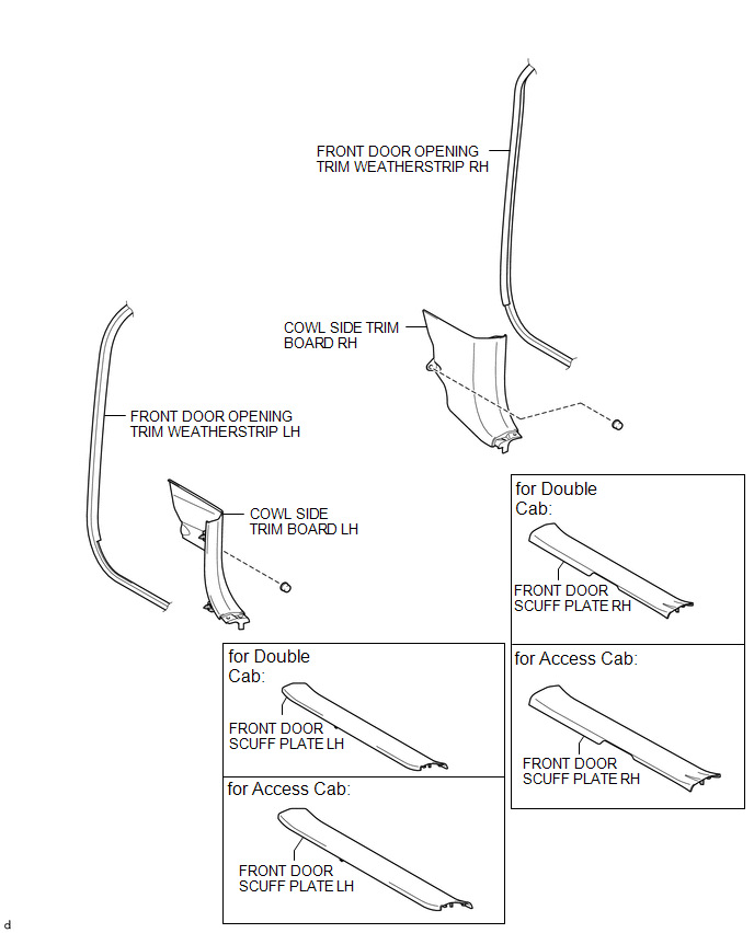
ILLUSTRATION
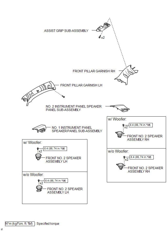
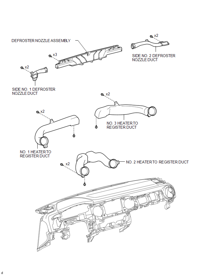
ILLUSTRATION
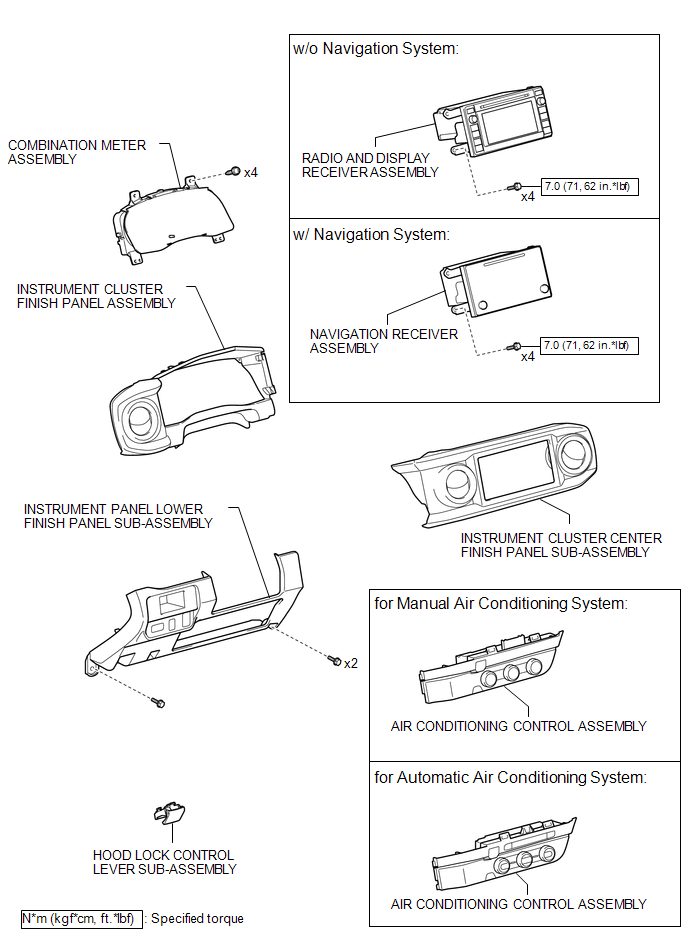
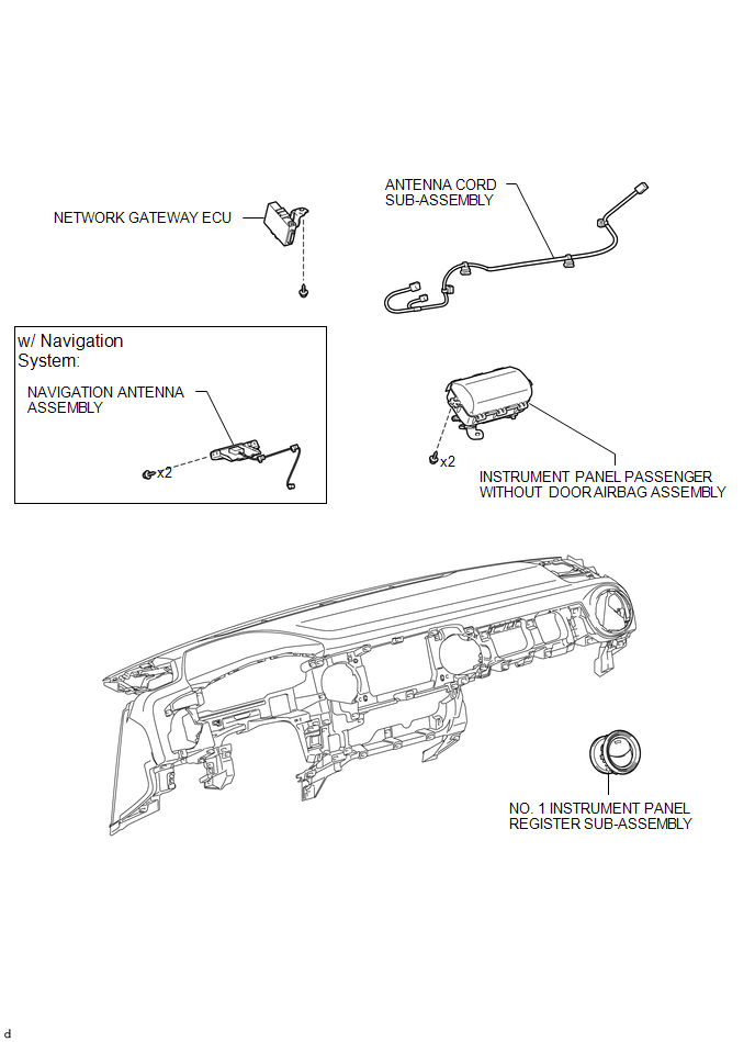
ILLUSTRATION
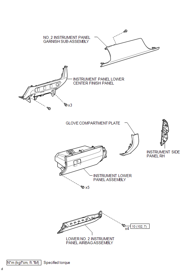
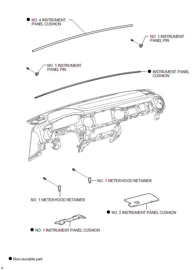
ILLUSTRATION
ILLUSTRATION
ILLUSTRATION
ILLUSTRATION
ILLUSTRATION
 Precaution
PRECAUTION
1. PRECAUTION FOR VEHICLE WITH SRS AIRBAG AND SEAT BELT PRETENSIONER
(a) Some operations in this section may affect the SRS airbags. Prior to performing
the corresponding operations, re ...
 Disassembly
DISASSEMBLY
PROCEDURE
1. REMOVE NO. 1 HEATER TO REGISTER DUCT
(a) Remove the 2 screws <F> and screw <D>.
(b) Disengage the 2 g ...
Other materials:
Open or Short in Front Speed Sensor RH Circuit (C1405,C1406)
DESCRIPTION
Refer to DTCs C1401 and C1402 (See page ).
DTC No.
Detection Item
DTC Detection Condition
Trouble Area
C1405
Open or Short in Front Speed Sensor RH Circuit
Either of the following is detected:
...
Automatic Disconnecting Differential Motor Control Circuit Open (P17A0)
DESCRIPTION
This DTC is output when an open circuit in the A.D.D. shift motor drive circuit
is detected.
DTC No.
Detection Item
DTC Detection Condition
Trouble Area
P17A0
Automatic Disconnecting Differential Motor Control Ci ...
Room Temperature Sensor Circuit (B1411/11)
DESCRIPTION
The cooler thermistor (room temperature sensor) is installed in the instrument
panel to detect the cabin temperature which is used to control the air conditioning
system AUTO mode. The resistance of the cooler thermistor (room temperature sensor)
changes in accordance with the cab ...
