Toyota Tacoma (2015-2018) Service Manual: Removal
REMOVAL
PROCEDURE
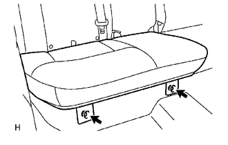
1. REMOVE REAR SEAT CUSHION ASSEMBLY
|
(a) Remove the 2 bolts and rear seat cushion assembly. |
|
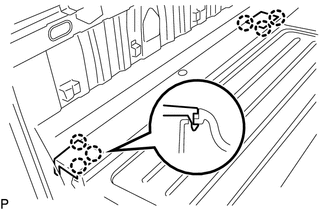
2. REMOVE REAR SEATBACK HINGE COVER
|
(a) Disengage the 6 claws to remove the 2 rear seatback hinge covers. |
|
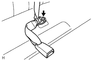
3. REMOVE REAR SEATBACK ASSEMBLY
|
(a) Remove the bolt to disconnect rear seat inner belt assembly and rear center seat outer belt assembly. |
|
|
(b) Remove the 2 bolts and rear seatback assembly. |
|
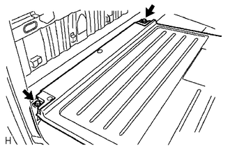
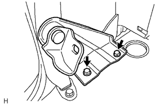
4. REMOVE REAR SEATBACK HINGE SUB-ASSEMBLY
|
(a) Remove the 2 bolts and rear seatback hinge sub-assembly. |
|
 Components
COMPONENTS
ILLUSTRATION
ILLUSTRATION
ILLUSTRATION
...
 Installation
INSTALLATION
PROCEDURE
1. INSTALL REAR SEATBACK HINGE SUB-ASSEMBLY
(a) Install the rear seatback hinge sub-assembly with the 2 bolts.
Torque:
30 N·m {306 kgf·cm, 22 ft·lbf}
2. INSTALL REAR S ...
Other materials:
Pressure Control Solenoid "A" Actuator Stuck Off (P07457F)
SYSTEM DESCRIPTION
The ECM uses the vehicle speed signal and signals from the transmission revolution
sensors (NT, SP2) to detect the actual gear (1st, 2nd, 3rd, 4th, 5th or 6th gear).
The ECM compares the actual gear with the shift schedule in the ECM memory to
detect mechanical problems of t ...
List of storage features
Glove box
Overhead console (Access Cab and
Double Cab models)
Bottle holders
Auxiliary boxes
Front console box (separated type
front seat only)
Cup holders
CAUTION
■Items that should not be left in the storage spaces
Do not leave glasses, lighters or spray cans in the stora ...
Inspection
INSPECTION
PROCEDURE
1. INSPECT TIE ROD END SUB-ASSEMBLY
(a) Flip the ball joint stud back and forth 5 times as shown in the illustration
before installing the nut.
(b) Using a torque wrench, turn the nut continuously at a rate of 2 to 4 seconds
per turn and check the torque reading on the ...
