Toyota Tacoma (2015-2018) Service Manual: Installation
INSTALLATION
PROCEDURE
1. INSTALL FRONT CONSOLE BOX (for Automatic Transmission)
|
(a) When installing a new front console box: Text in Illustration
(1) Using a nipper, cut off both ends of the runner portion as shown in the illustration. |
|
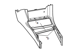
(b) Engage the 4 guides and 3 clips to install the front console box.
(c) Install the 3 screws.
(d) w/ Wireless Charger:
(1) Connect the connector.
2. INSTALL FRONT CONSOLE BOX (for Manual Transmission)
|
(a) When installing a new front console box: Text in Illustration
(1) Using a nipper, cut off both ends of the runner portion as shown in the illustration. |
|
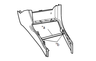
(b) Engage the 4 guides and 3 clips to install the front console box.
(c) Install the 2 screws.
(d) w/ Wireless Charger:
(1) Connect the connector.
3. INSTALL REAR CONSOLE BOX ASSEMBLY
(a) Engage the 4 guides and 2 claws to install the rear console box assembly.
(b) Engage the clamp and connect the connector.
(c) Install the 2 bolts.
4. INSTALL CONSOLE BOX CARPET
(a) Install the console box carpet.
5. INSTALL CONSOLE UPPER PANEL SUB-ASSEMBLY (for Automatic Transmission)
(a) Engage the 2 guides and 12 clips to install the console upper panel sub-assembly.
6. INSTALL CONSOLE UPPER PANEL SUB-ASSEMBLY (for Manual Transmission)
(a) Engage the 2 guides and 12 clips to install the console upper panel sub-assembly.
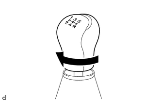
7. INSTALL SHIFT LEVER KNOB SUB-ASSEMBLY (for Automatic Transmission)
|
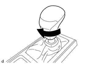
(a) Rotate the shift lever knob sub-assembly as shown in the illustration to install it. |
|
|
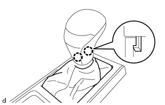
(b) Engage the 2 claws to install the shifting hole cover sub-assembly. |
|
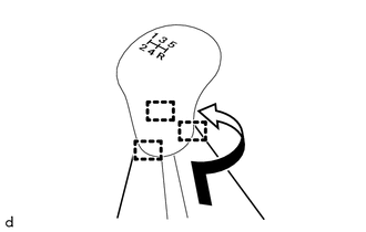
8. INSTALL SHIFT LEVER KNOB SUB-ASSEMBLY (for Manual Transmission)
|
(a) Rotate the shift lever knob sub-assembly as shown in the illustration to install it. |
|
|
(b) Engage the 3 guides to install the shifting hole cover sub-assembly as shown in the illustration. |
|
 Removal
REMOVAL
PROCEDURE
1. REMOVE SHIFT LEVER KNOB SUB-ASSEMBLY (for Automatic Transmission)
(a) Using a molding remover A, disengage the 2 claws to separate the
shifting hole cover sub-as ...
 Reassembly
REASSEMBLY
PROCEDURE
1. INSTALL CONSOLE COMPARTMENT DOOR HINGE SUB-ASSEMBLY
(a) Engage the 2 guides to install the console compartment door hinge
sub-assembly.
...
Other materials:
XM Tuner Antenna Disconnected (B15FE,B15FF)
DESCRIPTION
These DTCs are stored when a malfunction occurs in the antenna assembly with
holder which is connected to the radio and display receiver assembly.
DTC No.
DTC Detection Condition
Trouble Area
B15FE
The antenna assembly with ...
Installation
INSTALLATION
PROCEDURE
1. INSTALL REAR BUMPER ASSEMBLY
(a) Using an engine lifter or equivalent, engage the 2 pins to install the rear
bumper assembly as shown in the illustration.
Text in Illustration
*a
Pin
-
-
NOTICE:
Using pl ...
Problem Symptoms Table
PROBLEM SYMPTOMS TABLE
HINT:
Use the table below to help determine the cause of problem symptoms.
If multiple suspected areas are listed, the potential causes of the symptoms
are listed in order of probability in the "Suspected Area" column of the
table. Check each sy ...
