Toyota Tacoma (2015-2018) Service Manual: Removal
REMOVAL
PROCEDURE
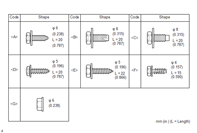
1. TABLE OF BOLT, SCREW AND NUT
HINT:
All bolts, screws and nuts relevant to installing and removing the instrument panel are shown along with their alphabetic codes in the table below.
2. PRECAUTION
NOTICE:
After turning the ignition switch off, waiting time may be required before disconnecting the cable from the negative (-) battery terminal. Therefore, make sure to read the disconnecting the cable from the negative (-) battery terminal notices before proceeding with work.
Click here .gif)
3. DISCONNECT CABLE FROM NEGATIVE BATTERY TERMINAL
NOTICE:
When disconnecting the cable, some systems need to be initialized after the cable is reconnected.
Click here
4. REMOVE FRONT CONSOLE BOX
Click here
5. REMOVE FRONT DOOR SCUFF PLATE LH (for Double Cab)
Click here
6. REMOVE FRONT DOOR SCUFF PLATE RH (for Double Cab)
HINT:
Use the same procedure as for the LH side.
7. REMOVE FRONT DOOR SCUFF PLATE LH (for Access Cab)
Click here
8. REMOVE FRONT DOOR SCUFF PLATE RH (for Access Cab)
HINT:
Use the same procedure as for the LH side.
9. REMOVE COWL SIDE TRIM BOARD LH
Click here
10. REMOVE COWL SIDE TRIM BOARD RH
HINT:
Use the same procedure as for the LH side.
11. DISCONNECT FRONT DOOR OPENING TRIM WEATHERSTRIP LH
(a) Disconnect the front door opening trim weatherstrip LH.
12. DISCONNECT FRONT DOOR OPENING TRIM WEATHERSTRIP RH
HINT:
Use the same procedure as for the LH side.
13. REMOVE FRONT PILLAR GARNISH LH
Click here
14. REMOVE ASSIST GRIP SUB-ASSEMBLY
Click here
15. REMOVE FRONT PILLAR GARNISH RH
Click here
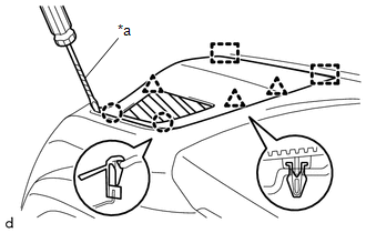
16. REMOVE NO. 1 INSTRUMENT PANEL SPEAKER PANEL SUB-ASSEMBLY
|
(a) Using a screwdriver with its tip wrapped in protective tape, disengage the 2 claws, 3 clips and 2 guides to remove the No. 1 instrument panel speaker panel sub-assembly. Text in Illustration
|
|
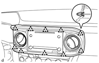
17. REMOVE NO. 2 INSTRUMENT PANEL SPEAKER PANEL SUB-ASSEMBLY
|
(a) Using a screwdriver with its tip wrapped in protective tape, disengage the 2 claws, 2 clips and 2 guides. Text in Illustration
|
|

(b) Disconnect the connector to remove the No. 2 instrument panel speaker panel sub-assembly.
18. REMOVE FRONT NO. 2 SPEAKER ASSEMBLY LH
Click here
19. REMOVE FRONT NO. 2 SPEAKER ASSEMBLY RH
Click here
20. REMOVE INSTRUMENT CLUSTER CENTER FINISH PANEL SUB-ASSEMBLY
|
(a) Disengage the 10 clips to remove the instrument cluster center finish panel sub-assembly. |
|
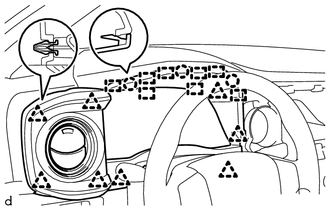
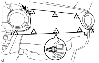
21. REMOVE INSTRUMENT CLUSTER FINISH PANEL ASSEMBLY
|
(a) Disengage the 8 clips, 3 claws and 8 guides to remove the instrument cluster finish panel assembly. |
|
22. REMOVE NAVIGATION RECEIVER ASSEMBLY (w/ Navigation System)
Click here
23. REMOVE RADIO AND DISPLAY RECEIVER ASSEMBLY (w/o Navigation System)
Click here
24. REMOVE COMBINATION METER ASSEMBLY
Click here
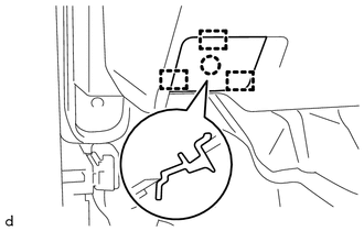
25. DISCONNECT HOOD LOCK CONTROL LEVER SUB-ASSEMBLY
|
(a) Disengage the claw and 3 guides to disconnect the hood lock control lever sub-assembly. |
|
26. REMOVE INSTRUMENT PANEL LOWER FINISH PANEL SUB-ASSEMBLY
|
(a) Remove the bolt <A>. |
|
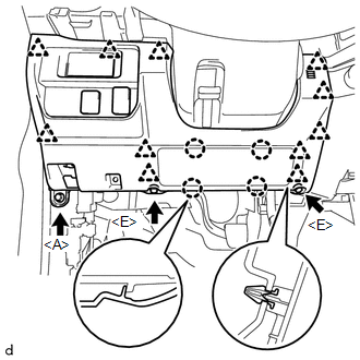
(b) Remove the 2 screws <E>.
(c) Disengage the 11 clips and 4 claws.
(d) Disconnect the connectors to remove the instrument panel lower finish panel sub-assembly.
27. REMOVE AIR CONDITIONING CONTROL ASSEMBLY (for Automatic Air Conditioning System)
Click here
28. REMOVE AIR CONDITIONING CONTROL ASSEMBLY (for Manual Air Conditioning System)
Click here
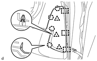
29. REMOVE INSTRUMENT SIDE PANEL RH
|
(a) Disengage the 4 claws, 3 clips and 3 guides to remove the instrument side panel RH. |
|
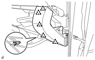
30. REMOVE GLOVE COMPARTMENT PLATE
|
(a) Disengage the 5 clips to remove the glove compartment plate. |
|
31. REMOVE LOWER NO. 2 INSTRUMENT PANEL AIRBAG ASSEMBLY
Click here
32. REMOVE INSTRUMENT LOWER PANEL ASSEMBLY
|
(a) Remove the 5 screws <F>. |
|
(b) Disengage the 4 clips to remove the instrument lower panel assembly.
33. REMOVE NO. 2 INSTRUMENT PANEL GARNISH SUB-ASSEMBLY
|
(a) Remove the screw <F>. |
|
(b) Disengage the 8 clips to remove the No. 2 instrument panel garnish sub-assembly.
34. REMOVE INSTRUMENT PANEL LOWER CENTER FINISH PANEL
|
(a) Remove the bolt <A>. |
|
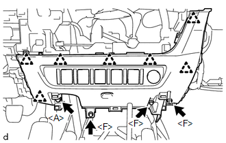
(b) Remove the 3 screws <F>.
(c) Disengage the 7 clips.
(d) Disconnect the connectors to remove the instrument panel lower center finish panel.
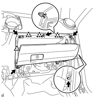
35. REMOVE INSTRUMENT PANEL SUB-ASSEMBLY
(a) Remove the 2 bolts <B> or 2 bolts <C>.
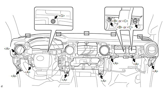
(b) Remove the 8 bolts <A>.
(c) Remove the nut <G>.
(d) Disconnect the connectors and disengage the clamps.
(e) Disengage the 5 guides to remove the instrument panel sub-assembly.
 Disassembly
DISASSEMBLY
PROCEDURE
1. REMOVE NO. 1 HEATER TO REGISTER DUCT
(a) Remove the 2 screws <F> and screw <D>.
(b) Disengage the 2 g ...
 Installation
INSTALLATION
PROCEDURE
1. INSTALL INSTRUMENT PANEL SUB-ASSEMBLY
(a) Engage the 5 guides to install the instrument panel sub-assembly.
(b) Engage the clamps and connect the connectors.
(c) Insta ...
Other materials:
Perchlorate Material
Special handling may apply, See www.dtsc.ca.gov/hazardouswaste/perchlorate.
Your vehicle has components that may contain perchlorate. These components may
include airbag, seat belt pretensioners, and wireless remote control batteries.
CAUTION
■General precautions while driving
Driving un ...
VSC Buzzer Circuit
DESCRIPTION
The skid control ECU (brake actuator assembly) is connected to the combination
meter via CAN communication.
The combination meter has a built-in VSC warning buzzer:
Sounds intermittently to inform the driver if the temperature of brake
actuator assembly has increased exce ...
Operation Check
OPERATION CHECK
1. INSPECT INTERIOR LIGHT CONTROL OPERATION
NOTICE:
Perform this inspection with the customize parameters at the default settings.
The interior light control illuminates the lights below.
Engine Switch Illumination*1
Transponder Key Coil (Ignition Key Cylinder Light)* ...
